List of related manuals
GENERAL MANUALS
RPBA-01 PROFIBUS DP Adapter User's Manual
SREA-01 Ethernet Adapter User's Manual
ACS550-01/U1 User's Manual (0.75…160 kW) /
(1…200 hp)
Typical contents
• Safety
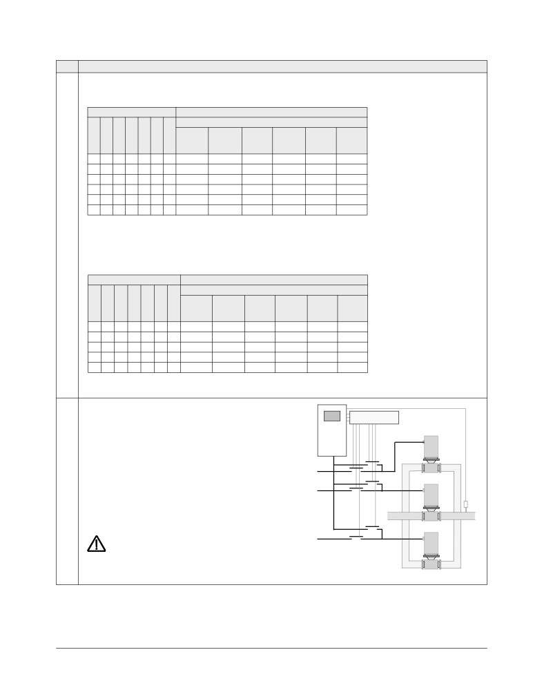
Flange Mounting Instructions
• Installation
Kit, IP21 / UL type 1
Frame size Code (English)
• Programming/Start-up
FMK-A-R1
R1
• Diagnostics
FMK-A-R2
R2
• Technical data
FMK-A-R3
R3
FMK-A-R4
R4
MAINTENANCE MANUALS
AC8-FLNGMT-R5 1
R5
ACS800-
1
AC8-FLNGMT-R6
R6
PNTG01U-EN
Guide for Capacitor Reforming in ACS50, ACS55,
1. Not available for ACS550-01 series
ACS150, ACS310, ACS350, ACS355, ACS550, ACH550
and R1-R4 OINT-/SINT-boards
Kit, IP54 / UL type 12
Frame size Code (English)
FMK-B-R1
R1
FMK-B-R2
R2
FMK-B-R3
R3
FMK-B-R4
R4
OPTION MANUALS
(delivered with optional equipment)
MFDT-01 FlashDrop User's Manual
OHDI-01 115/230 V Digital Input Module User's Manual
OREL-01 Relay Output Extension Module User's
Manual
OTAC-01 User’s Manual Pulse Encoder Interface
Module User’s Manual
RCAN-01 CANopen Adapter User's Manual
CANopen is a registered trademark of CAN in Automation
e.V.
RCNA-01 ControlNet Adapter User's Manual
ControlNet™ is a trademark of ODVA™.
RDNA-01 DeviceNet Adapter User's Manual
DeviceNet™ is a trademark of ODVA™.
DRIVECOM is a registered trademark of DRIVECOM User
RECA-01 EtherCAT Adapter Module User's Manual
Group e.V.
EtherCAT® is registered trademark and patented
REPL-01 Ethernet POWERLINK Adapter Module
technology, licensed by Beckhoff Automation GmbH,
User's Manual
Germany.
EtherNet/IP™ is a trademark of ODVA™.
REPL-02 Ethernet POWERLINK Adapter Module
ETHERNET POWERLINK is a trademark of Bernecker +
User's Manual
Rainer Industrie-ElektronikGes.m.b.H.
Modbus and Modbus/TCP are registered trademarks of
RETA-01 Ethernet Adapter Module User's Manual
Schneider Automation Inc.
PROFIBUS, PROFIBUS DP and PROFINET IO are
RETA-02 Ethernet Adapter Module User's Manual
registered trademarks of Profibus International.
ACS550-01/U1 Drives
0.75…160 kW
1…200 hp
User’s Manual
3AFE64804588 (3AUA0000001418) Rev H
EN
EFFECTIVE: 2014-07-04
SUPERSEDES: 3AFE64804588 (3AUA0000001418) Rev G 2009-07-07
2014 ABB Oy. All Rights Reserved.
ACS550-01/U1 User’s Manual
5
Safety instructions
Use of warnings and notes
There are two types of safety instructions throughout this manual:
• Notes draw attention to a particular condition or fact, or give information on a
subject.
• Warnings caution you about conditions which can result in serious injury or death
and/or damage to the equipment. They also tell you how to avoid the danger. The
warning symbols are used as follows:
Electricity warning warns of hazards from electricity which can cause physical
injury and/or damage to the equipment.
General warning warns about conditions, other than those caused by electricity,
which can result in physical injury and/or damage to the equipment.
General safety
WARNING! Obey these instructions. If you ignore them, injury or death, or damage
to the equipment can occur.
• Use safety shoes to avoid foot injury.
• Handle the drive carefully.
• Beware of hot surfaces. Some parts, such as heatsinks, remain hot for a while
after disconnection of the electrical supply. See chapter Technical data on page
277.
• Keep the drive in its package or protect it otherwise from dust and burr from
drilling and grinding until you install it. Protect also the installed drive against dust
and burr. Electrically conductive debris inside the drive can cause damage or
malfunction.
Electrical safety
WARNING! The ACS550 adjustable speed AC drive should ONLY be installed by a
qualified electrician.
WARNING! Even when the motor is stopped, dangerous voltage is present at the
power circuit terminals U1, V1, W1 and U2, V2, W2 and, depending on the frame
size, UDC+ and UDC-, or BRK+ and BRK-.
Safety instructions
6
ACS550-01/U1 User’s Manual
WARNING! Dangerous voltage is present when input power is connected. After
disconnecting the supply, wait at least 5 minutes (to let the intermediate circuit
capacitors discharge) before removing the cover.
WARNING! Even when power is switched off from the input terminals of the
ACS550, there may be dangerous voltage (from external sources) on the terminals
of the relay outputs RO1…RO3.
WARNING! When the control terminals of two or more drives are connected in
parallel, the auxiliary voltage for these control connections must be taken from a
single source which can either be one of the drives or an external supply.
WARNING! If you install the drive on an IT system (an ungrounded power system or
a high-resistance-grounded [over 30 ohms] power system), disconnect the internal
EMC filter, otherwise the system will be connected to ground potential through the
EMC filter capacitors. This can cause danger or damage the drive.
If you install the drive on a corner-grounded TN system, disconnect the internal EMC
filter, otherwise the system will be connected to ground potential through the EMC
filter capacitors. This will damage the drive.
Note: Disconnecting the internal EMC filter increases the conducted emission and
reduces the drive EMC compatibility considerably.
See section Disconnecting the internal EMC filter on page 27. Also see sections IT
systems on page 286 and Corner-grounded TN systems on page 285.
WARNING! Do not attempt to install or remove EM1, EM3, F1 or F2 screws while
power is applied to the drive’s input terminals.
Maintenance
WARNING! The ACS550-01/U1 is not field repairable. Never attempt to repair a
malfunctioning drive; contact your local ABB representative for replacement.
Safety instructions
ACS550-01/U1 User’s Manual
7
Control of the drive and motor
WARNING! Do not control the motor with the disconnecting device (disconnecting
means); instead, use the control panel start and stop keys
and
, or
commands via the I/O board of the drive. The maximum allowed number of charging
cycles of the DC capacitors (i.e. power-ups by applying power) is five in ten minutes.
WARNING! The ACS550 will start up automatically after an input voltage interruption
if the external run command is on.
Note: For more technical information, contact your local ABB representative.
Safety instructions
8
ACS550-01/U1 User’s Manual
Safety instructions
ACS550-01/U1 User’s Manual
9
Table of contents
List of related manuals
Safety instructions
Use of warnings and notes
5
General safety
5
Electrical safety
5
Maintenance
6
Control of the drive and motor
7
Table of contents
Contents of this manual
Compatibility
13
Intended use
13
Intended audience
13
Installation
Installation flow chart
15
Preparing for installation
16
Installing the drive
20
Start-up, control with I/O and ID Run
How to start up the drive
37
How to control the drive through the I/O interface
44
How to perform the ID Run
45
Control panels
About control panels
47
Compatibility
47
Assistant Control Panel
48
Basic Control Panel
68
Application macros
ABB Standard macro
78
3-wire macro
79
Alternate macro
80
Motor Potentiometer macro
81
Hand-Auto macro
82
PID Control macro
83
PFC macro
84
Torque Control macro
85
Connection examples of two-wire and three-wire sensors
86
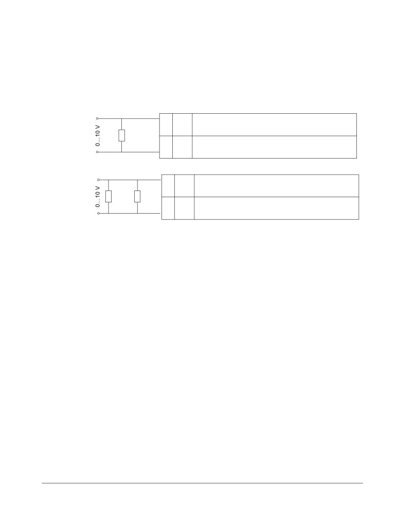
Connection for obtaining 0…10 V from analog outputs
87
User parameter sets
88
Table of contents
10
ACS550-01/U1 User’s Manual
Macro default values for parameters
89
Parameters
Complete parameter list
91
Complete parameter descriptions
106
Embedded fieldbus
Overview
203
Planning
204
Mechanical and electrical installation - EFB
204
Communication set-up - EFB
205
Activate drive control functions - EFB
207
Feedback from the drive - EFB
211
Diagnostics - EFB
212
Modbus protocol technical data
215
ABB control profiles technical data
224
Fieldbus adapter
Overview
237
Planning
239
Mechanical and electrical installation - FBA
240
Communication set-up - FBA
241
Activate drive control functions - FBA
241
Feedback from the drive - FBA
244
Diagnostics - FBA
245
ABB Drives profile technical data
248
Generic profile technical data
256
Diagnostics
Diagnostic displays
259
Correcting faults
260
Correcting alarms
266
Maintenance
Maintenance intervals
271
Heatsink
271
Main fan replacement
272
Internal enclosure fan replacement
274
Capacitors
275
Control panel
275
Technical data
Ratings
277
Input power connections
281
Motor connections
289
Brake components
295
Control connections
299
Efficiency
300
Losses, cooling data and noise
301
Table of contents
ACS550-01/U1 User’s Manual
11
Dimensions and weights
303
Degrees of protection
306
Ambient conditions
307
Materials
308
Applicable standards
309
Markings
309
IEC/EN 61800-3:2004 Definitions
311
Compliance with the IEC/EN 61800-3:2004 +A1:2012
311
Index
Further information
Product and service inquiries
325
Product training
325
Providing feedback on ABB Drives manuals
325
Document library on the Internet
325
Table of contents
12
ACS550-01/U1 User’s Manual
Table of contents
ACS550-01/U1 User’s Manual
13
Contents of this manual
Compatibility
This manual covers ACS550-01/U1 drives. The manual is compatible with the
ACS550-01/U1 drive firmware version 3.14e or later. See parameter 3301
FIRMWARE on page 155.
Intended use
The ACS550-01/U1 is a general purpose drive. The macros should only be applied
to the applications defined in the respective section.
Intended audience
This manual is intended for personnel who install, commission, operate and service
the drive. Read the manual before working on the drive. The reader is expected to
know the fundamentals of electricity, wiring, electrical components and electrical
schematic symbols.
Contents of this manual
14
ACS550-01/U1 User’s Manual
Contents of this manual
ACS550-01/U1 User’s Manual
15
Installation
Study these installation instructions carefully before proceeding. Failure to observe
the warnings and instructions may cause a malfunction or personal hazard.
WARNING! Before you begin read chapter Safety instructions on page 5.
Note: The installation must always be designed and made according to applicable
local laws and regulations. ABB does not assume any liability whatsoever for any
installation which breaches the local laws and/or other regulations. Furthermore, if
the recommendations given by ABB are not followed, the drive may experience
problems that the warranty does not cover.
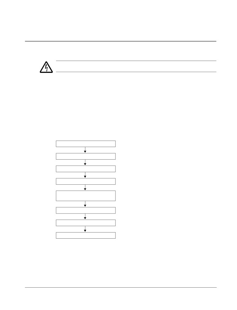
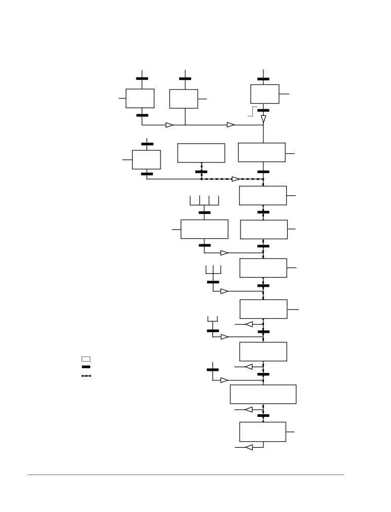
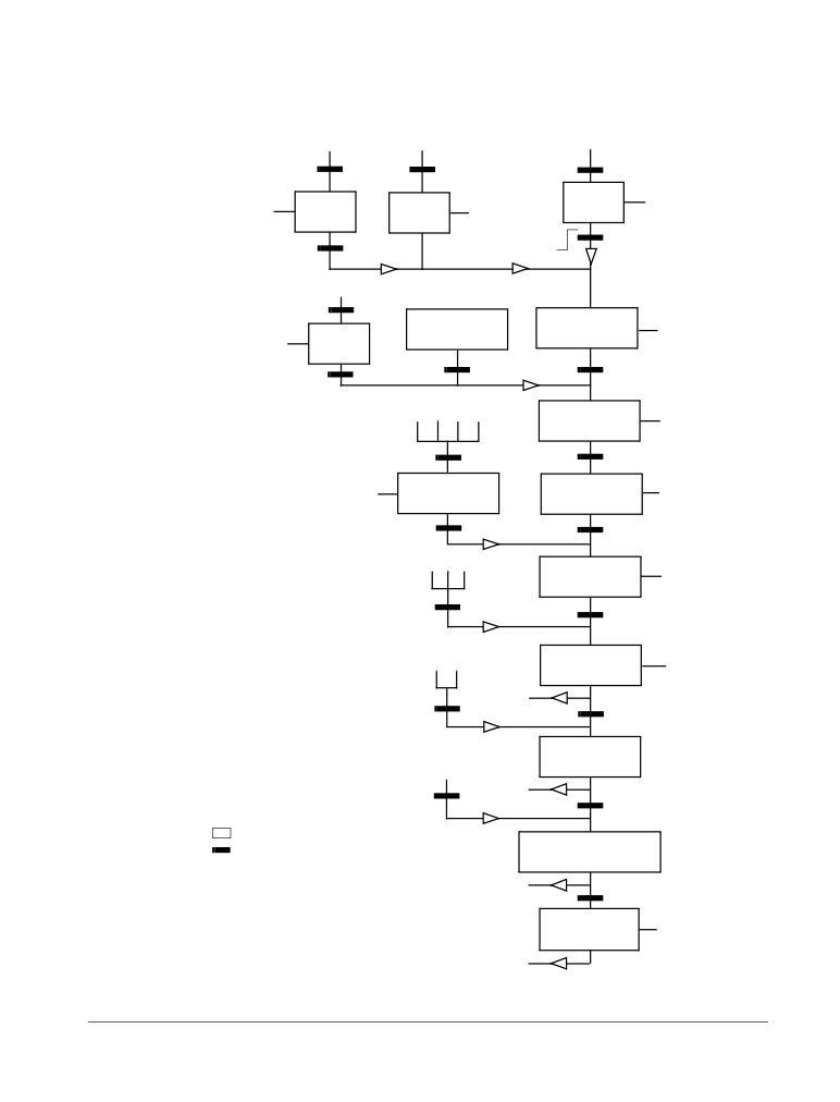
Installation flow chart
The installation of the ACS550 adjustable speed AC drive follows the outline below.
The steps must be carried out in the order shown. At the right of each step are
references to the detailed information needed for the correct installation of the drive.
Task
See
PREPARE for installation
Preparing for installation on page 16
PREPARE the mounting location
Prepare the mounting location on page 20
REMOVE the front cover
Remove the front cover on page 21
MOUNT the drive
Mount the drive on page 22
INSTALL wiring
Wiring overview on page 23 and
Check the insulation of the assembly on page 30
CHECK installation
Check installation on page 35
REINSTALL the cover
Reinstall the cover on page 36
START-UP
How to start up the drive on page 37
Installation
16
ACS550-01/U1 User’s Manual
Preparing for installation
Lifting the drive
Lift the drive only by the metal
chassis.
Unpacking the drive
1. Unpack the drive.
2. Check for any damage and
notify the shipper immediately
if damaged components are
found.
IP2040
3. Check the contents against
the order and the shipping label to verify that all parts have been received.
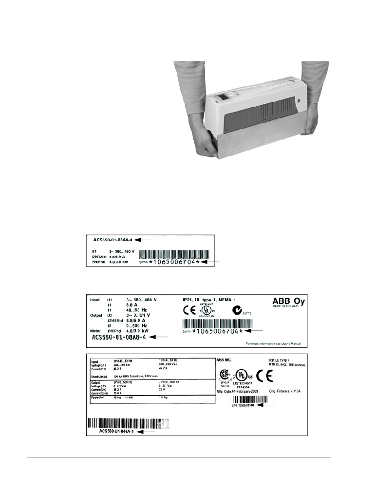
Drive identification
Drive labels
To determine the type of drive you are installing, refer to either:
• serial number label attached on upper part of the choke plate between the
mounting holes, or
Type designation
Serial number
• type designation label attached on the heat sink - on the right side of the drive
cover. Two examples of the type designation label are given below.
Serial number
Type designation
Serial number
Type designation
Installation
ACS550-01/U1 User’s Manual
17
The labels contain information on the Type designation (page 17), Ratings and frame
size (page 17), Serial number (page 17), degree of protection (see also Degrees of
protection on page 306) and valid markings (see also Markings on page 309).
Type designation
Use the following chart to interpret the type designation found on both the type
designation and the serial number label.
ACS550-01-08A8-4+J404+…
AC, Standard Drive - 550 product series
Construction (region specific)
01 = Setup and parts specific to IEC installation and compliance
U1= Setup and parts specific to US installation and NEMA compliance
Output current rating
e.g. 08A8 = 8.8 A, see section Ratings on page 277 for details
Voltage rating
2 = 208…240 VAC
4 = 380…480 VAC
6 = 500…600 VAC
Options
Examples of options:
B055 = IP54 / UL type 12 (no specification = IP21 / UL type 1).
UL type 12 is not available for type ACS550-01-290A-4.
0J400 = No control panel
J404
= ACS-CP-C Basic Control Panel
L511
= OREL-01
Relay output extension
K451 = RDNA-01
DeviceNet
K454 = RPBA-01
PROFIBUS DP
Ratings and frame size
The chart in section Ratings on page 277 lists technical specifications and identifies
the drive’s frame size - significant, since some instructions in this document vary,
depending on the drive’s frame size. To read the ratings table, you need the “Output
current rating” entry from the type designation. Also, when using the ratings table,
note that the table is broken into sections based on the drive’s “Voltage rating”.
Serial number
The format of the drive serial number shown on the labels is described below.
Serial number is of format CYYWWXXXXX, where
C:
Country of manufacture
YY:
Year of manufacture
WW:
Week of manufacture; 01, 02, 03, … for week 1, week 2, week 3, …
XXXXX:
Integer starting every week from 00001.
Installation
18
ACS550-01/U1 User’s Manual
Motor compatibility
The motor, drive and supply power must be compatible:
Motor
Verify
Reference
specification
Motor type
3-phase induction motor
-
Nominal current
Motor value is within this
• Type designation label on drive, entry for
range: 0.2…2.0 · I2hd
Output I2hd, or
(I2hd = drive heavy duty
• Type designation on drive and rating table in
current)
chapter Technical data on page 277.
Nominal frequency
10…500 Hz
-
Voltage range
Motor is compatible with
208…240 V (for ACS550-X1-XXXX-2) or
the ACS550 voltage range.
380…480 V (for ACS550-X1-XXXX-4) or
500…600 V (for ACS550-U1-XXXX-6)
Insulation
500…600 V drives: Either
For ACS550-U1-XXXX-6
the motor complies with
NEMA MG1 Part 31, or a
du/dt filter is used between
the motor and drive.
Tools required
To install the ACS550 you need the following:
• screwdrivers (as appropriate for the mounting hardware used)
• wire stripper
• tape measure
• drill
• for installations involving ACS550-U1, frame sizes R5 or R6 and IP54 / UL type
12 enclosures: punch for creating conduit mounting holes
• for installations involving ACS550-U1, frame size R6: appropriate crimping tool
for power cable lugs. See section Power terminal considerations - R6 frame size
on page 287.
• mounting hardware: screws or nuts and bolts, four each. The type of hardware
depends on the mounting surface and the frame size. For the dimensions and
weights of the frames, see Dimensions and weights on page 303.
Frame size
Mounting hardware
R1…R4
M5
#10
R5
M6
1/4 in
R6
M8
5/16 in
Suitable environment and enclosure
Confirm that the site meets the environmental requirements. To prevent damage
prior to installation, store and transport the drive according to the environmental
requirements specified for storage and transportation. See section Ambient
conditions on page 307.
Installation
ACS550-01/U1 User’s Manual
19
Confirm that the enclosure is appropriate, based on the site contamination level:
• IP21 / UL type 1 enclosure: The site must be free of airborne dust, corrosive
gases or liquids, and conductive contaminants such as dripping water,
condensation, carbon dust and metallic particles.
• IP54 / UL type 12 enclosure: This enclosure provides protection from airborne
dust and light sprays or splashing water from all directions.
• If, for some reason, an IP21 drive needs to be installed without the conduit box or
cover, or an IP54 drive without the conduit plate or hood, see the note in chapter
Technical data, page 310.
Suitable mounting location
Confirm that the mounting location meets the following constraints:
• The drive must be mounted vertically on a smooth, solid surface, and in a suitable
environment as defined above. For horizontal installation, contact your local ABB
representative for more information.
• The minimum space requirements for the drive are the outside dimensions (see
section Outside dimensions on page 304), plus air flow space around the drive
(see section Losses, cooling data and noise on page 301).
• The distance between the motor and the drive is limited by the maximum motor
cable length. See section Motor connection specifications on page 289.
• The mounting site must support the drive’s modest weight. See section Weight on
page 306.
Installation
20
ACS550-01/U1 User’s Manual
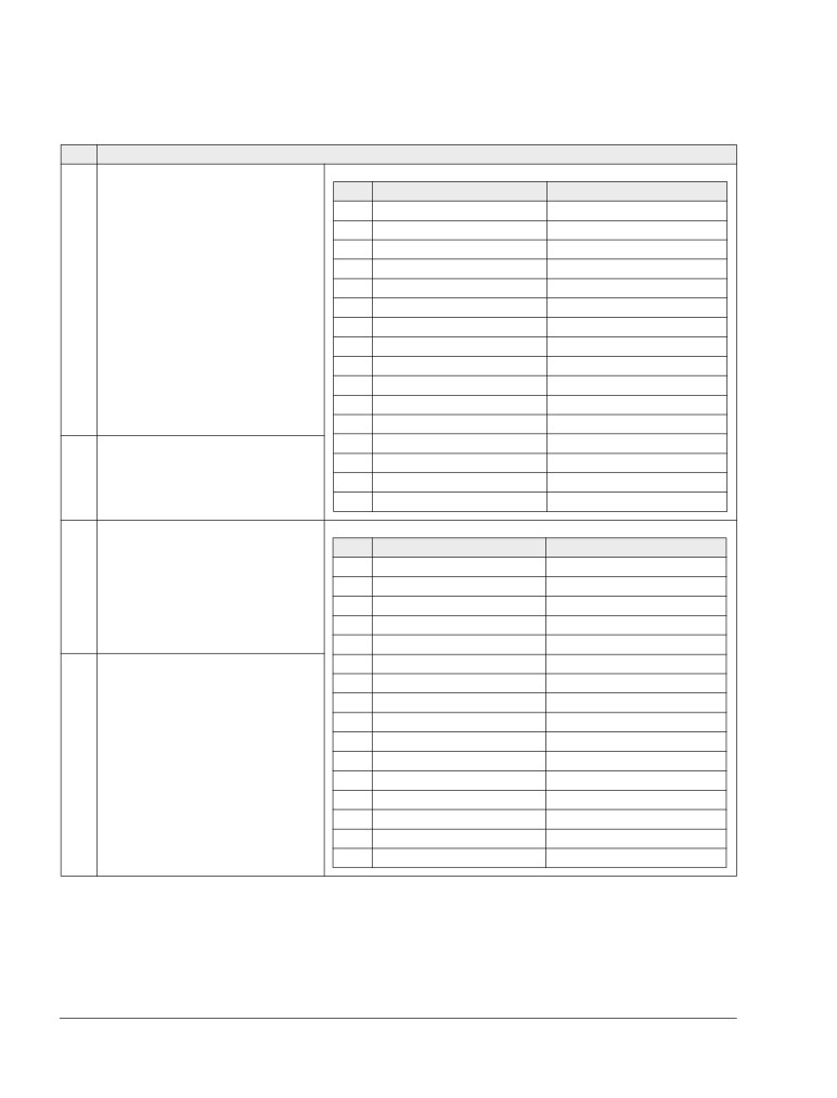
Installing the drive
WARNING! Before installing the ACS550, ensure the input power supply to the drive
is off.
For flange mounting (mounting the drive in a cooling air duct), see the appropriate
Flange Mounting Instructions:
IP21 / UL type 1
IP54 / UL type 12
Frame size
Kit
Code (English)
Kit
Code (English)
R1
FMK-A-R1
100000982
FMK-B-R1
100000990
R2
FMK-A-R2
100000984
FMK-B-R2
100000992
R3
FMK-A-R3
100000986
FMK-B-R3
100000994
R4
FMK-A-R4
100000988
FMK-B-R4
100000996
R5
AC8-FLNGMT-R5 1
ACS800-PNTG01U-
-
-
EN
R6
AC8-FLNGMT-R6 1
-
-
1. Not available in ACS550-01 series.
Prepare the mounting location
The ACS550 should only be mounted where all of the
requirements defined in section Preparing for installation
on page 16 are met.
1. Mark the position of the mounting holes with the help of
1
the mounting template provided with the drive.
X0002
2. Drill the holes.
Note: Frame sizes R3 and R4 have four holes along the top. Use only two. If
possible, use the two outside holes (to allow room to remove the fan for
maintenance).
Note: ACS400 drives can be replaced using the original mounting holes. For R1 and
R2 frame sizes, the mounting holes are identical. For R3 and R4 frame sizes, the
inside mounting holes on the top of ACS550 drives match ACS400 mounts.
Installation
ACS550-01/U1 User’s Manual
21
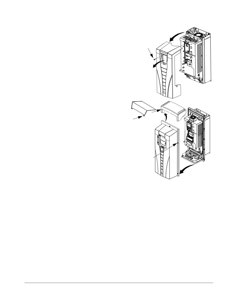
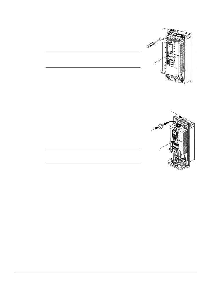
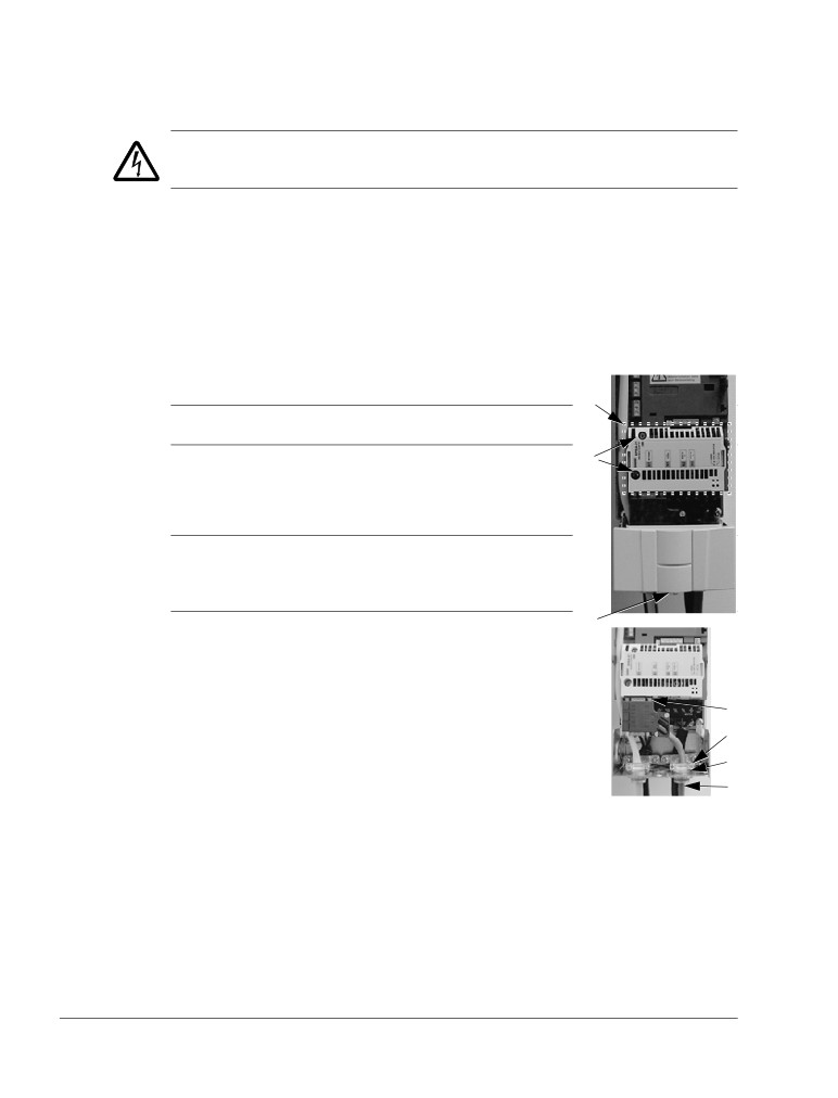
Remove the front cover
3
IP21 / UL type 1
1. Remove the control panel, if attached.
2
2. Loosen the captive screw at the top.
3. Pull near the top to remove the
cover.
1
IP2000
IP54 / UL type 12
R6
R1…R5
1. If hood is present: Remove screws
1
(2) holding hood in place.
2
1
2. If hood is present: Slide hood up and
off of the cover.
3. Loosen the captive screws around
the edge of the cover.
4. Remove the cover.
3
4
FM
Installation
22
ACS550-01/U1 User’s Manual
Mount the drive
1
IP21 / UL type 1
1. Position the ACS550 onto the mounting screws or
bolts and securely tighten in all four corners.
Note: Lift the ACS550 by its metal chassis (frame
size R6 by the lifting holes on both sides at the top).
2
2. Non-English speaking locations: Add a warning
sticker in the appropriate language over the existing
warning on the top of the module.
IP2002
IP54 / UL type 12
For the IP54 / UL type 12 enclosures, rubber plugs are required in the holes
provided for access to the drive mounting slots.
1. As required for access, remove the rubber plugs.
3
Push plugs out from the back of the drive.
2. R5 & R6: Align the sheet metal hood (not shown) in
front of the drive’s top mounting holes. (Attach as
part of next step.)
1, 4
3. Position the ACS550 onto the mounting screws or
bolts and securely tighten in all four corners.
5
Note: Lift the ACS550 by its metal chassis (frame
size R6 by the lifting holes on both sides at the top).
FM
4. Reinstall the rubber plugs.
5. Non-English speaking locations: Add a warning sticker in the appropriate language
over the existing warning on the top of the module.
Installation
ACS550-01/U1 User’s Manual
23
Wiring overview
Conduit/Gland kit
Wiring drives with the IP21 / UL type 1 enclosure requires a conduit/gland kit with the
following items:
• conduit/gland box
• five (5) cable clamps (ACS550-01 only)
• screws
• cover.
The kit is included with IP21 / UL type 1 enclosures.
Wiring requirements
WARNING! Ensure the motor is compatible for use with the ACS550. The drive must
be installed by a competent person in accordance with the considerations defined in
section Preparing for installation on page 16. If in doubt, contact your local ABB
representative.
As you install the wiring, observe the following:
•
There are four sets of wiring instructions - one set for each combination of drive
enclosure type (IP21 / UL type and IP54 / UL type 12) and wiring type (conduit or
cable). Be sure to select the appropriate procedure.
•
Determine electro-magnetic compliance (EMC) requirements per local codes.
See section Motor cable requirements for CE & C-Tick compliance on page 293.
In general:
- Follow local codes for cable size.
- Keep these four classes of wiring separated: input power wiring, motor wiring,
control/communications wiring and braking unit wiring.
•
When installing input power and motor wiring, refer to the following, as
appropriate:
Terminal
Description
Specifications and notes
U1, V1, W11
3-phase power supply input
Input power connections on page 281
PE
Protective Ground
Ground connections on page 285
U2, V2, W2
Power output to motor
Motor connections on page 289
1 The ACS550 -x1-xxxx-2 (208…240 V series) can be used with a single phase supply, if output
current is derated by 50%. For single phase supply voltage, connect power at U1 and W1.
•
To locate input power and motor connection terminals, see section Power
connection diagrams on page 25. For specifications on power terminals, see
section Drive’s power connection terminals on page 286.
•
For corner-grounded TN systems, see section Corner-grounded TN systems on
page 285.
•
For IT systems, see section IT systems on page 286.
Installation
24
ACS550-01/U1 User’s Manual
•
For frame size R6, see section Power terminal considerations - R6 frame size on
page 287 to install the appropriate cable lugs.
•
For drives using braking (optional), refer to the following, as appropriate:
Frame size
Terminal
Description
Braking accessory
R1, R2
BRK+, BRK-
Braking resistor
Braking resistor. See section Brake
components on page 295.
R3, R4, R5, R6
UDC+, UDC-
DC bus
Contact your ABB representative to
order either:
• braking unit or
• chopper and resistor
•
When installing control wiring, refer to the following chapters or sections, as
appropriate:
- Control terminals table on page 28
- Control connections on page 299
- Application macros on page 77
- Complete parameter descriptions on page 106
- Embedded fieldbus on page 203
- Fieldbus adapter on page 237.
Installation
ACS550-01/U1 User’s Manual
25
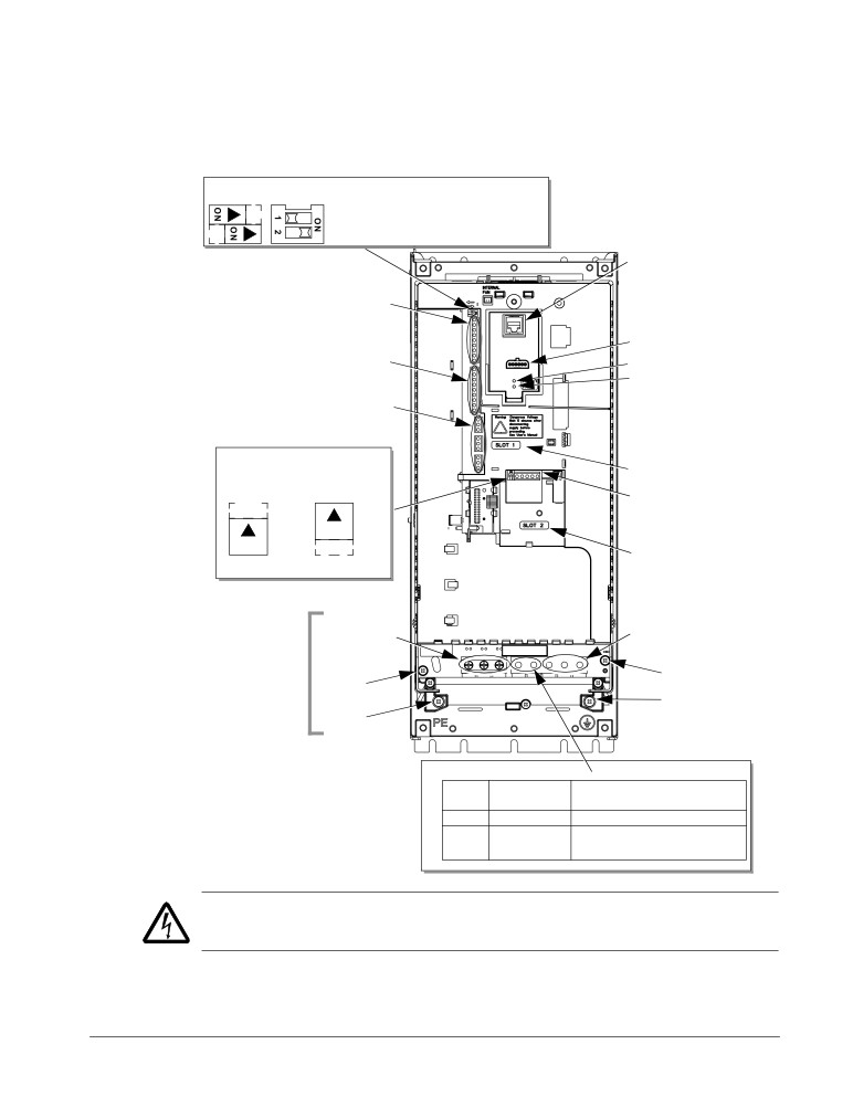
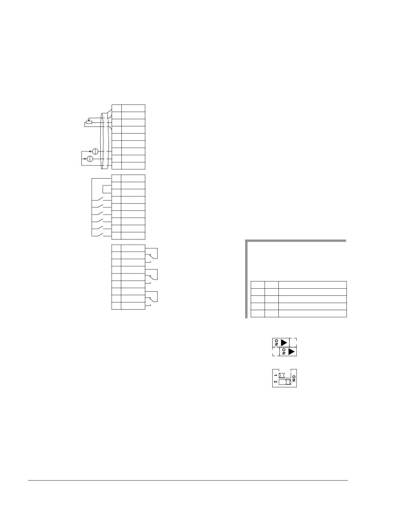
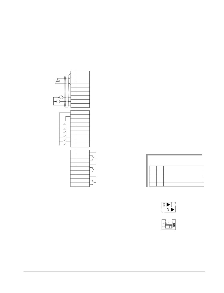
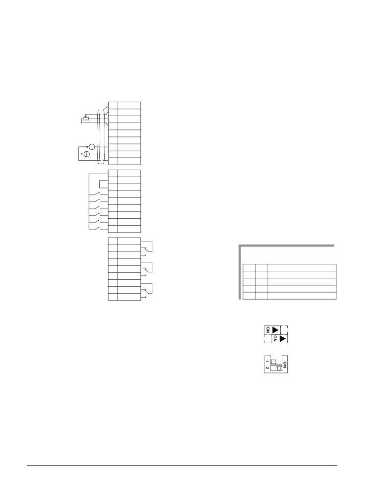
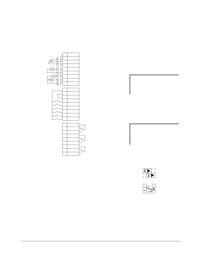
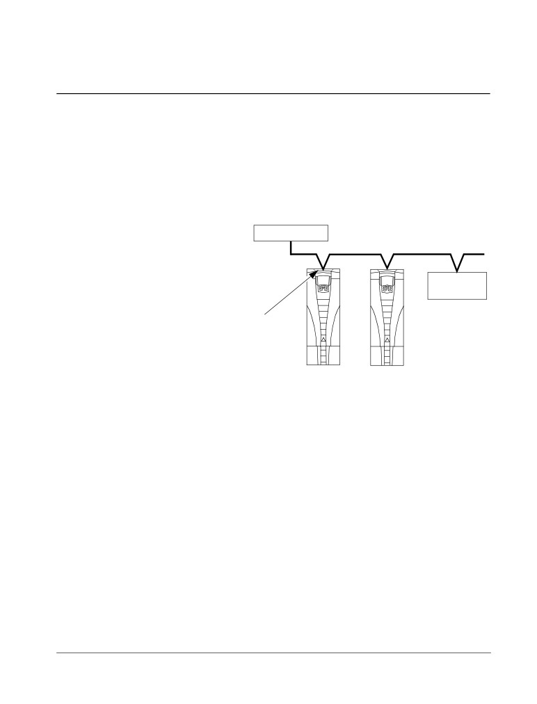
Power connection diagrams
The following diagram shows the terminal layout for frame size R3, which, in
general, applies to frame sizes R1…R6, except for the R5/R6 power and ground
terminals.
J1 - DIP switches for analog inputs (two types can be used)
J1
J1
Diagram shows the R3 frame.
AI1: (in voltage position)
Other frames have similar layouts.
AI2: (in current position)
Panel connector
X1 - Analog inputs and outputs
(and 10 V ref. voltage output)
FlashDrop option
X1 - Digital inputs
Power LED (green)
(and 24 V aux. voltage output)
Fault LED (red)
X1 - Relay outputs
J2 - DIP switch
for RS485 termination
Optional module 1
J2
J2
X1 - Communications
(RS485)
ON
ON
Optional module 2
off position
on position
Power input
Power output to motor
(U1, V1, W1)
(U2, V2, W2)
Frame sizes
R5/R6 differ.
See
EM3
next page.
EM1
GND
PE
3AUA0000001571
Optional braking
Frame
Terminal
Brake options
size
labels
R1, R2
BRK+, BRK-
Brake resistor
R3, R4
UDC+, UDC-
• Braking unit
• Chopper and resistor
WARNING! To avoid danger, or damage to the drive, on IT systems and corner-
grounded TN systems, see section Disconnecting the internal EMC filter on page 27.
Installation
26
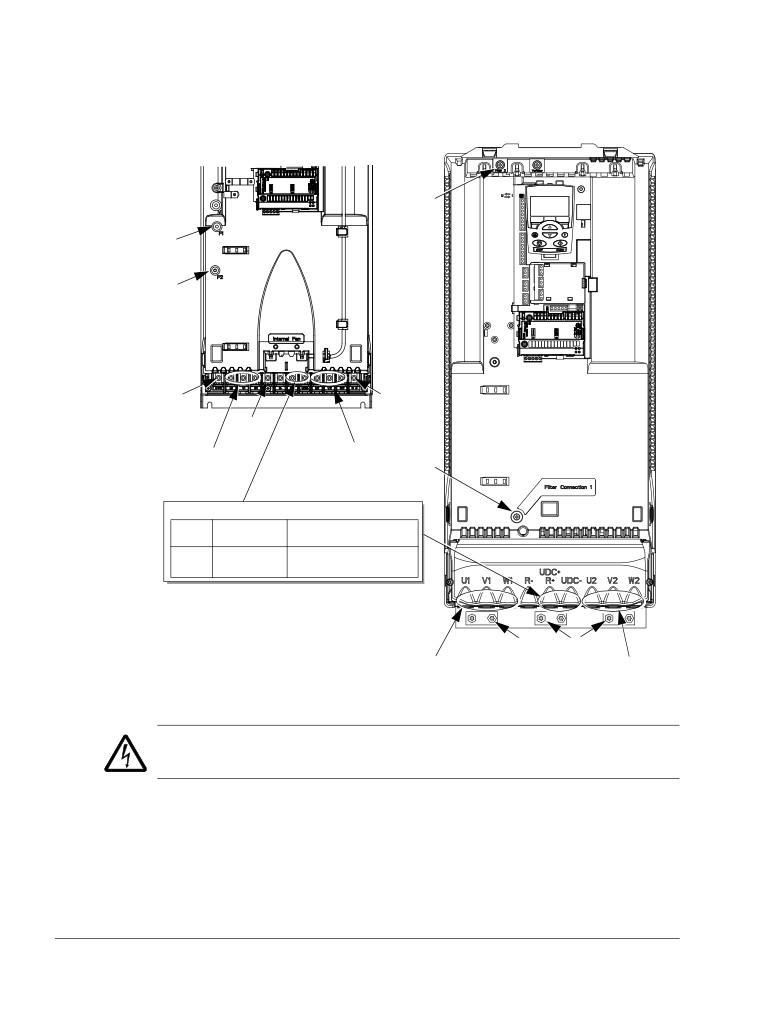
ACS550-01/U1 User’s Manual
The following diagram shows the power and ground terminal layout for frame sizes
R5 and R6end
R5
R6
F2
F1
F2
PE
GND
X0011
GND
Power input
Power output to motor
(U1, V1, W1)
(U2, V2, W2)
F1
Optional braking
Frame
Terminal
Brake options
size
labels
R5, R6
UDC+, UDC-
• Braking unit
• Chopper and resistor
X0013
PE
GND
Power input
Power output to motor
(U1, V1, W1)
(U2, V2, W2)
WARNING! To avoid danger, or damage to the drive, on IT systems and corner-
grounded TN systems, see section Disconnecting the internal EMC filter on page 27.
Installation
ACS550-01/U1 User’s Manual
27
Disconnecting the internal EMC filter
On certain types of systems, you must disconnect the internal EMC filter, otherwise
the system will be connected to ground potential through the EMC filter capacitors,
which might cause danger, or damage the drive.
Note: Disconnecting the internal EMC filter increases the conducted emission and
reduces the drive EMC compatibility considerably.
The following table shows the installation rules for the EMC filter screws in order to
connect or disconnect the filter, depending on the system type and the frame size.
For more information on the different system types, see IT systems on page 286 and
Corner-grounded TN systems on page 285.
The locations of screws EM1 and EM3 are shown in the diagram on page 25. The
locations of screws F1 and F2 are shown in the diagram on page 26.
Symmetrically
IT systems (ungrounded
Frame
Corner-grounded
Screw
grounded TN systems
or high-resistance-
sizes
TN systems
(TN-S systems)
grounded [> 30 ohm])
EM1
x
x
R1…R3
EM31
x
EM1
x
x
-
R4
EM31
x
-
-
F1
x
x
-
R5…R6
F2
x
x
-
x = Install the screw. (EMC filter will be connected.)
= Replace the screw with the provided polyamide screw. (EMC filter will be disconnected.)
- = Remove the screw. (EMC filter will be disconnected.)
1 ACS550-U1 drives are shipped with screw EM3 already removed.
Installation
28
ACS550-01/U1 User’s Manual
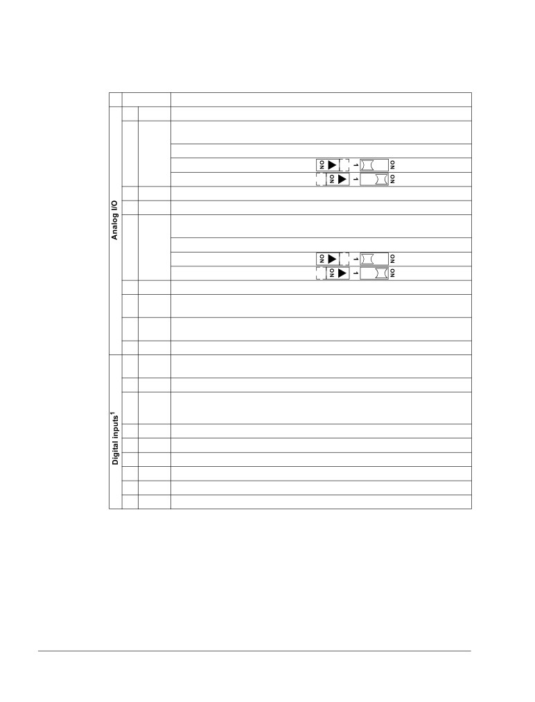
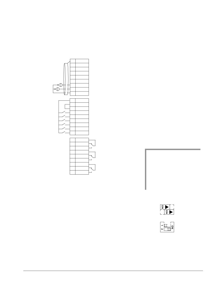
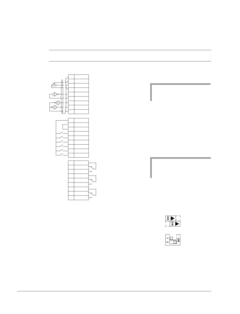
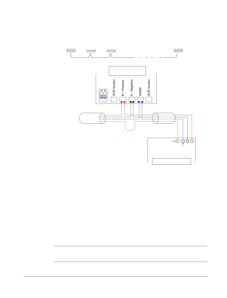
Control terminals table
The following provides information for connecting control wiring at X1 on the drive.
X1
Hardware description
1
SCR
Terminal for signal cable shield (screen). (Connected internally to chassis ground.)
2
AI1
Analog input channel 1, programmable. Default2 = frequency reference. Resolution
0.1%, accuracy ±1%.
Two different DIP switch types can be used.
J1: AI1 OFF: 0…10 V (Ri = 312 kohm)
J1: AI1 ON: 0…20 mA (Ri = 100 ohm)
3
AGND
Analog input circuit common (connected internally to chassis gnd. through 1 Mohm).
4
+10 V
Potentiometer reference source: 10 V ±2%, max. 10 mA (1 kohm < R < 10 kohm).
5
AI2
Analog input channel 2, programmable. Default2 = not used. Resolution 0.1%,
accuracy ±1%.
Two different DIP switch types can be used.
J1: AI2 OFF: 0…10 V (Ri = 312 kohm)
J1: AI2 ON: 0…20 mA (Ri = 100 ohm)
6
AGND
Analog input circuit common (connected internally to chassis gnd. through 1 Mohm).
7
AO1
Analog output, programmable. Default2 = frequency. 0…20 mA (load < 500 ohm).
Accuracy ±3%.
8
AO2
Analog output, programmable. Default2 = current. 0…20 mA (load < 500 ohm).
Accuracy ±3%.
9
AGND
Analog output circuit common (connected internally to chassis gnd. through 1 Mohm).
10
+24V
Auxiliary voltage output 24 V DC / 250 mA (reference to GND), short circuit
protected.
11
GND
Auxiliary voltage output common (connected internally as floating).
12
DCOM
Digital input common. To activate a digital input, there must be 10 V
(or -10 V) between that input and DCOM. The 24 V may be provided by the
ACS550 (X1-10) or by an external 12…24 V source of either polarity.
13
DI1
Digital input 1, programmable. Default2 = start/stop.
14
DI2
Digital input 2, programmable. Default2 = fwd/rev.
15
DI3
Digital input 3, programmable. Default2 = constant speed sel (code).
16
DI4
Digital input 4, programmable. Default2 = constant speed sel (code).
17
DI5
Digital input 5, programmable. Default2 = ramp pair selection (code).
18
DI6
Digital input 6, programmable. Default2 = not used.
Installation
ACS550-01/U1 User’s Manual
29
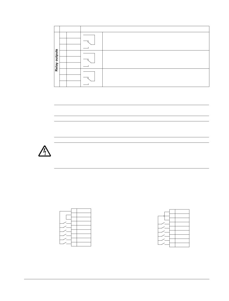
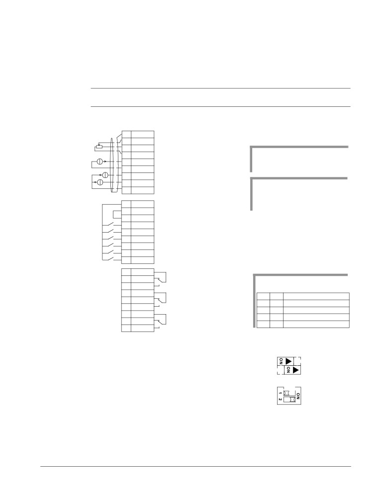
X1
Hardware description
19
RO1C
Relay output 1, programmable. Default2 = Ready
Maximum: 250 V AC / 30 V DC, 2 A
20
RO1A
Minimum: 500 mW (12 V, 10 mA)
21
RO1B
22
RO2C
Relay output 2, programmable. Default2 = Running
Maximum: 250 V AC / 30 V DC, 2 A
23
RO2A
Minimum: 500 mW (12 V, 10 mA)
24
RO2B
25
RO3C
Relay output 3, programmable. Default2 = Fault (-1)
Maximum: 250 V AC / 30 V DC, 2 A
26
RO3A
Minimum: 500 mW (12 V, 10 mA)
27
RO3B
1 Digital input impedance 1.5 kohm. Maximum voltage for digital inputs is 30 V.
2 Default values depend on the macro used. Values specified are for the default macro. See chapter
Application macros on page 77.
Note: Terminals 3, 6 and 9 are at the same potential.
Note: For safety reasons the fault relay signals a “fault” when the ACS550 is
powered down.
WARNING! All ELV (Extra Low Voltage) circuits connected to the drive must be used
within a zone of equipotential bonding, i.e. within a zone where all simultaneously
accessible conductive parts are electrically connected to prevent hazardous voltages
appearing between them. This is accomplished by a proper factory grounding.
The terminals on the control board as well as on the optional modules attachable to
the board fulfil the Protective Extra Low Voltage (PELV) requirements stated in
EN 50178, provided that the external circuits connected to the terminals also fulfil
the requirements and the installation site is below 2000 m (6562 ft).
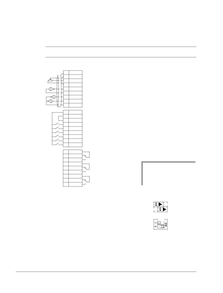
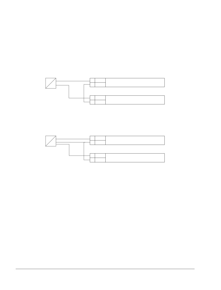
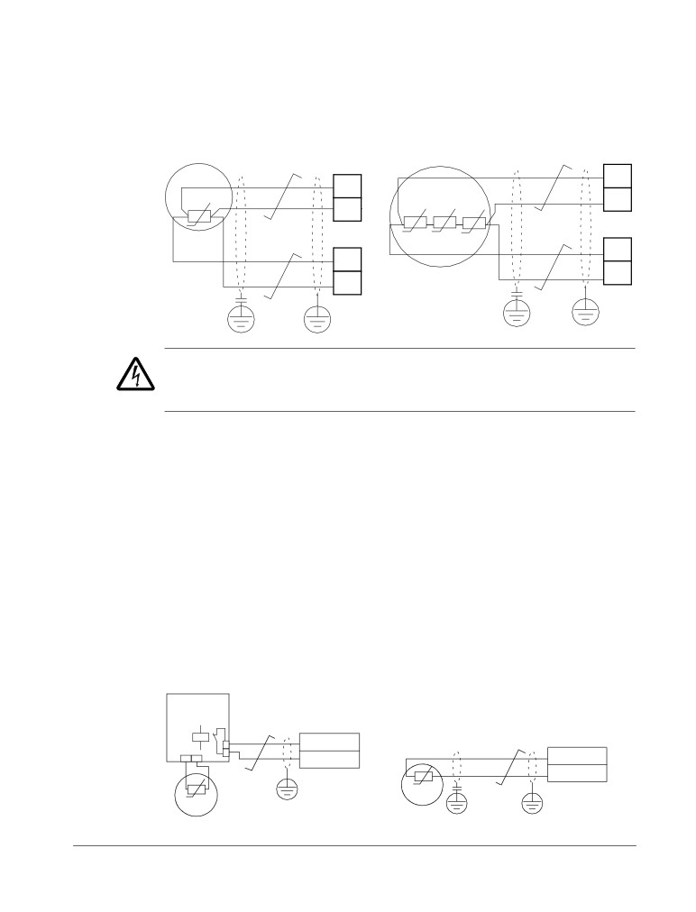
You can wire the digital input terminals in either a PNP or NPN configuration.
PNP connection (source)
NPN connection (sink)
X1
X1
10
+24V
10
+24V
11
GND
11
GND
12
DCOM
12
DCOM
13
DI1
13
DI1
14
DI2
14
DI2
15
DI3
15
DI3
16
DI4
16
DI4
17
DI5
17
DI5
18
DI6
18
DI6
Installation
30
ACS550-01/U1 User’s Manual
Check the insulation of the assembly
Drive
Do not make any voltage tolerance or insulation resistance tests on any part of the
drive as testing can damage the drive. Every drive has been tested for insulation
between the main circuit and the chassis at the factory. Also, there are voltage-
limiting circuits inside the drive which cut down the testing voltage automatically.
Supply cable
Check the insulation of the supply (input) cable according to local regulations before
connecting to the drive.
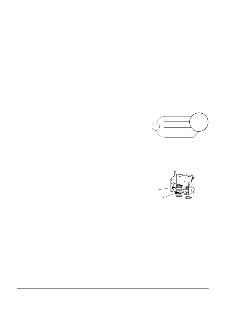
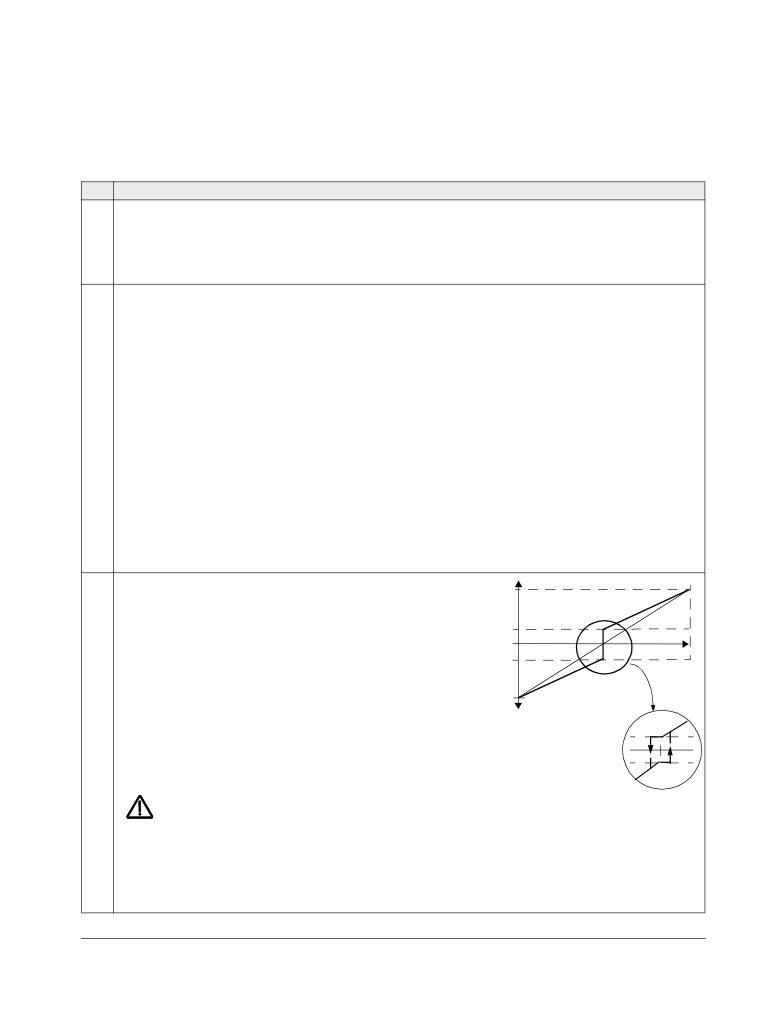
Motor and motor cable
Check the insulation of the motor and motor cable as follows:
1. Check that the motor cable is connected to the motor, and disconnected from the
drive output terminals U2, V2 and W2.
2. Measure the insulation resistance between phase
U1
conductors and between each phase conductor and
M
V1
the Protective Earth conductor using a measuring
3~
ohm
voltage of 1000 V DC. The insulation resistance of an
W1 PE
ABB motor must exceed 100 Mohm (reference value
at 25 °C or 77 °F). For the insulation resistance of
other motors, please consult the manufacturer’s instructions. Note: Moisture inside
the motor casing will reduce the insulation resistance. If moisture is suspected, dry
the motor and repeat the measurement.
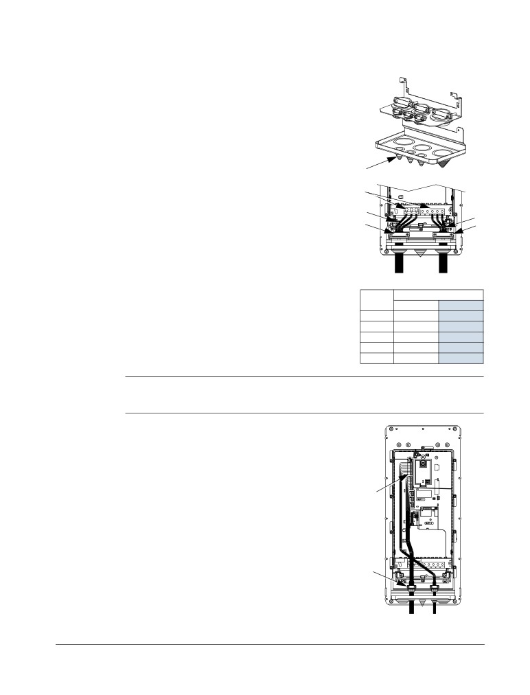
Install the wiring
Wiring IP21 / UL type 1 enclosure with cables
1. Open the appropriate knockouts in the conduit/gland
box. (See section Conduit/Gland kit on page 23.)
2
2. Install the cable clamps for the power/motor cables.
1
X0004
Installation
ACS550-01/U1 User’s Manual
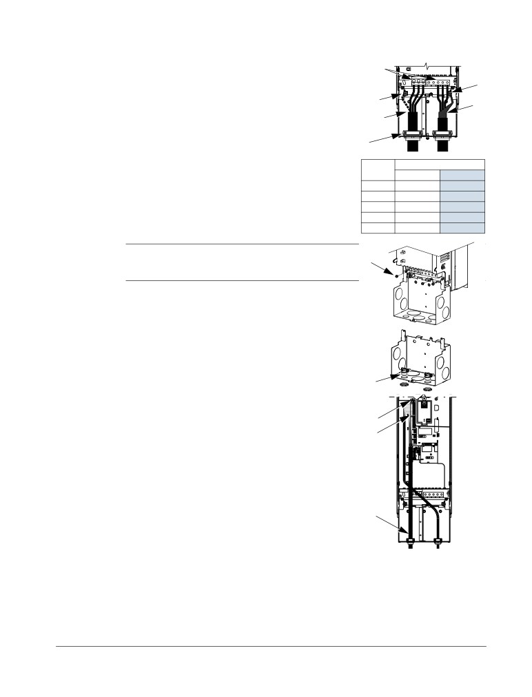
31
3.
On the input power cable, strip the sheathing back far
6
enough to route individual wires.
7
4.
On the motor cable, strip the sheathing back far
6
enough to expose the copper wire shield so that the
4
shield can be twisted into a bundle (pig-tail). Keep the
3
bundle not longer than five times its width to minimize
noise radiation.
8
IP2001
360° grounding under the clamp is recommended for
the motor cable to minimize noise radiation. In this
Frame
Tightening torque
case, remove the sheathing at the cable clamp.
size
N·m
lb·ft
R1, R2
1.4
1
5.
Route both cables through the clamps.
R3
2.5
1.8
6.
Strip and connect the power/motor wires and the
R4
5.6; PE: 2
4; PE 1.5
power ground wire to the drive terminals. See the
R5
15
11
table on the right for tightening torques.
R6
40; PE: 8
30; PE: 6
Note: For R6 frame size, refer to section Power
8
terminal considerations - R6 frame size on page 287.
7.
Connect the bundle (pig-tail) created from the motor
cable shield to the GND terminal.
X0005
8.
Install conduit/gland box and tighten the cable clamps.
9.
Install the cable clamp(s) for the control cable(s).
(Power/motor cables and clamps not shown in the
figure.)
9
X0006
10.
Strip control cable sheathing and twist the copper
shield into a bundle (pig-tail).
12
11.
Route control cable(s) through clamp(s) and tighten
13
clamp(s).
12.
Connect the ground shield bundle (pig-tail) for digital and
analog I/O cables at X1-1. (Ground only at the drive end.)
13.
Strip and connect the individual control wires to the
drive terminals. See section Control terminals table
on page 28. Use a tightening torque of 0.4 N·m
11
(0.3 lb·ft).
14.
Install the conduit/gland box cover (1 screw).
IP2003
Installation
32
ACS550-01/U1 User’s Manual
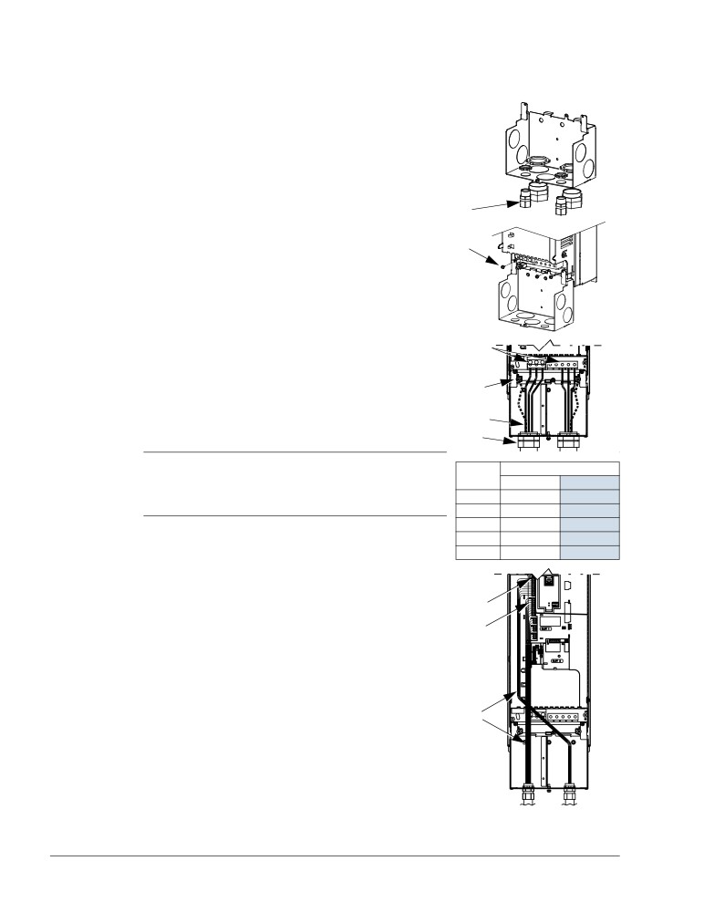
Wiring IP21 / UL type 1 enclosure with conduit
1. Open the appropriate knockouts in the conduit/gland
box. (See section Conduit/Gland kit on page 23.)
2. Install thin-wall conduit clamps (not supplied).
2
X0007
3. Install conduit/gland box.
3
4. Connect conduit runs to box.
X0005
5.
Route input power and motor wiring through
7
conduits (must be separate conduit runs).
6.
Strip wires.
7
7.
Connect power, motor and ground wires to the drive
terminals. See the table on the right for tightening
5
torques.
4
IP2004
Note: For R6 frame size, refer to section Power
Frame
Tightening torque
terminal considerations - R6 frame size on page
size
N·m
lb·ft
287.
R1, R2
1.4
1
R3
2.5
1.8
R4
5.6; PE: 2
4; PE 1.5
R5
15
11
R6
40; PE: 8
30; PE: 6
8.
Route the control cable through the conduit (must be
separate from input power and motor conduit runs).
10
9.
Strip the control cable sheathing and twist the copper
shield into a bundle (pig-tail).
11
10.
Connect the ground shield bundle (pig-tail) for digital
and analog I/O cables at X1-1. (Ground only at the
drive end.)
11.
Strip and connect the individual control wires to the
drive terminals. See section Control terminals table
8
on page 28. Use a tightening torque of 0.4 N·m
(0.3 lb·ft).
12.
Install the conduit/gland box cover (1 screw).
IP2005
Installation
ACS550-01/U1 User’s Manual
33
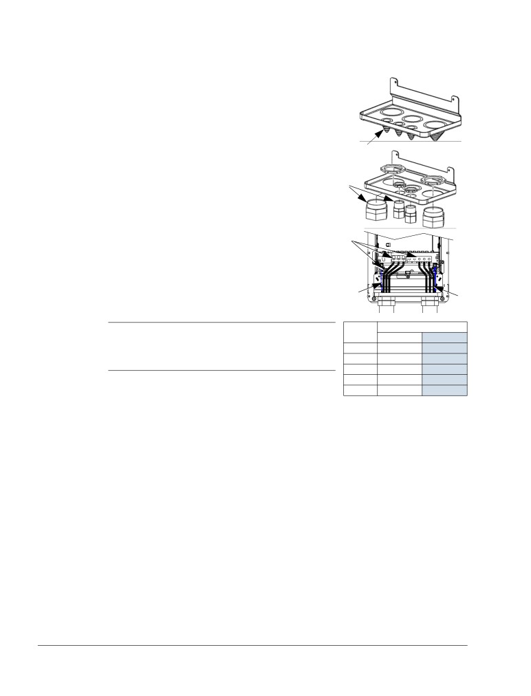
Wiring IP54 / UL type 12 enclosure with cables
1.
Cut the cable seals as needed for the power, motor
and control cables. The cable seals are cone-
shaped, rubber seals on the bottom of the drive.
The conical part of the seals must face downwards
when the seals are inserted in the lead-through
plate holes.
IP5003
1
2.
On the input power cable, strip the sheathing back
far enough to route individual wires.
5
3.
On the motor cable, strip the sheathing back far
enough to expose the copper wire shield so that
2
3
4
the shield can be twisted into a bundle (pig-tail).
4
Keep the bundle not longer than five times its width
to minimize noise radiation.
360° grounding under the clamp is recommended
IP5004
for the motor cable to minimize noise radiation. In
this case, remove the sheathing at the cable
clamp.
Frame
Tightening torque
size
N·m
lb·ft
4.
Route both cables through the clamps and tighten
R1, R2
1.4
1
the clamps.
R3
2.5
1.8
5.
Strip and connect the power/motor wires and the
R4
5.6; PE: 2
4; PE 1.5
R5
15
11
power ground wire to the drive terminals. See the
R6
40; PE: 8
30; PE: 6
table on the right for tightening torques.
Note: For R6 frame size, refer to section Power terminal considerations - R6 frame
size on page 287.
6.
Connect the bundle (pig-tail) created from the
motor cable shield to the GND terminal.
7.
Strip control cable sheathing and twist the copper
shield into a bundle (pig-tail).
8.
Route control cable(s) through clamp(s) and
9, 10
tighten clamp(s).
9.
Connect the ground shield bundle (pig-tail) for
digital and analog I/O cables at X1-1. (Ground only
at the drive end.)
10.
Strip and connect the individual control wires to the
drive terminals. See section Control terminals table
8
on page 28. Use a tightening torque of 0.4 N·m
(0.3 lb·ft).
IP5005
Installation
34
ACS550-01/U1 User’s Manual
Wiring IP54 / UL type 12 enclosure with conduit
1. Remove and discard the cable seals where conduit
will be installed. (The cable seals are cone-shaped,
rubber seals on the bottom of the drive.)
IP5013
1
2. For each conduit run, install water tight conduit
connectors (not supplied).
2
IP5016
3. Route the power wiring through the conduit.
6
4. Route the motor wiring through the conduit.
5. Strip the wires.
6. Connect the power, motor and ground wires to the
3
drive terminals. See the table on the right for
4
tightening torques.
IP5007
Frame
Tightening torque
Note: For R6 frame size, refer to section Power
sizeN·m
lb·ft
terminal considerations - R6 frame size on page
R1, R2
1.4
1
287.
R3
2.5
1.8
R4
5.6; PE: 2
4; PE 1.5
R5
15
11
7. Route the control cable through the conduit.
R6
40; PE: 8
30; PE: 6
8. Strip the control cable sheathing and twist the
copper shield into a bundle (pig-tail).
9. Connect the ground shield bundle (pig-tail) for digital and analog I/O cables at X1-1.
(Ground only at the drive end.)
10. Strip and connect the individual control wires to the drive terminals. See section
Control terminals table on page 28. Use a tightening torque of 0.4 N·m (0.3 lb·ft).
Installation
ACS550-01/U1 User’s Manual
35
Check installation
Before applying power, perform the following checks.
Check
Installation environment conforms to the drive’s specifications for ambient conditions.
The drive is mounted securely.
Space around the drive meets the drive’s specifications for cooling.
The motor and driven equipment are ready for start.
For IT systems and corner-grounded TN systems: The internal EMC filter is disconnected (see
section Disconnecting the internal EMC filter on page 27).
The drive is properly grounded.
The input power (mains) voltage matches the drive nominal input voltage.
The input power (mains) connections at U1, V1 and W1 are connected and tightened as
specified.
The input power (mains) fuses are installed.
The motor connections at U2, V2 and W2 are connected and tightened as specified.
The motor cable is routed away from other cables.
NO power factor compensation capacitors are in the motor cable.
The control connections are connected and tightened as specified.
NO tools or foreign objects (such as drill shavings) are inside the drive.
NO alternate power source for the motor (such as a bypass connection) is connected - no
voltage is applied to the output of the drive.
Installation
36
ACS550-01/U1 User’s Manual
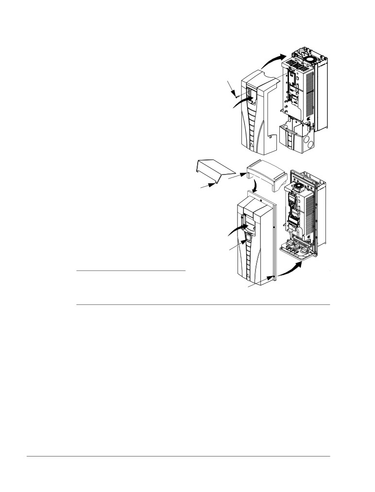
Reinstall the cover
1
IP21 / UL type 1
1. Align the cover and slide it on.
2
2. Tighten the captive screw.
3. Reinstall the control panel.
4. Continue with start-up. See chapter Start-up,
3
control with I/O and ID Run on
page 37.
IP2009
IP54 / UL type 12
R6
R1…R5
1. Align the cover and slide it on.
4
2. Tighten the captive screws around
3
4
the edge of the cover.
3. Slide the hood down over the top
of the cover. (Only needed for UL
type 12 installations.)
4. Install the two screws that attach
5
the hood. (Only needed for UL
type 12 installations.)
6
5. Install the control panel.
1
Note: The control panel window
must be closed to comply with
2
FM
IP54 / UL type 12.
6. Optional: Add a lock (not supplied) to secure the control panel window.
7. Continue with start-up. See chapter Start-up, control with I/O and ID Run on page
37.
Installation
ACS550-01/U1 User’s Manual
37
Start-up, control with I/O and ID Run
The chapter instructs how to:
• perform the start-up
• start, stop, change the direction of rotation and adjust the speed of the motor
through the I/O interface
• perform an Identification Run for the drive.
Using the control panel to do these tasks is explained briefly in this chapter. For
details on how to use the control panel, refer to chapter Control panels starting on
page 47.
How to start up the drive
How you start up the drive depends on the control panel you have.
• If you have an Assistant Control Panel, you can either run the Start-up
Assistant (see section How to perform the guided start-up on page 42) or perform
a limited start-up (see section How to perform the limited start-up on page 37).
The Start-up Assistant, which is included in the Assistant Control Panel only,
guides you through all essential settings to be done. In the limited start-up, the
drive gives no guidance; you go through the very basic settings by following the
instructions given in the manual.
• If you have a Basic Control Panel, follow the instructions given in section How
to perform the limited start-up on page 37.
How to perform the limited start-up
For the limited start-up, you can use the Basic Control Panel or the Assistant Control
Panel. The instructions below are valid for both control panels, but the displays
shown are the Basic Control Panel displays, unless the instruction applies to the
Assistant Control Panel only.
Before you start, ensure that you have the motor nameplate data on hand.
SAFETY
The start-up may only be carried out by a qualified electrician.
The safety instructions given in chapter Safety instructions must be followed during
the start-up procedure.
The drive will start up automatically at power up, if the external run command is on.
Check the installation. See the checklist in chapter Installation, page 35.
Start-up, control with I/O and ID Run
38
ACS550-01/U1 User’s Manual
Check that the starting of the motor does not cause any danger.
De-couple the driven machine if:
• there is a risk of damage in case of incorrect direction of rotation, or
• an ID Run needs to be performed during the drive start-up. ID Run is essential only in
applications that require the ultimate in motor control accuracy.
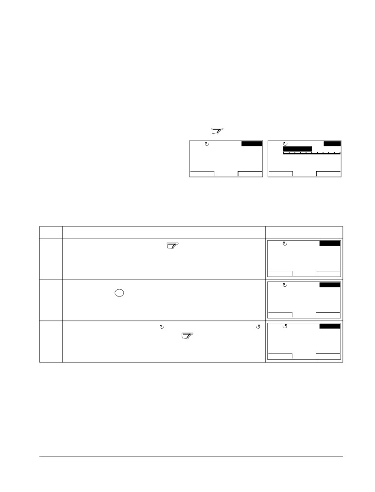
POWER-UP
Apply input power.
REM
Hz
The Basic Control Panel powers up into the Output mode.
OUTPUT
FWD
The Assistant Control Panel asks if you want to run the Start-
REM
CHOICE
EXIT
Do you want to
up Assistant. If you press
, the Start-up Assistant is not
use the start-up
assistant?
run, and you can continue with manual start-up in a similar
Yes
manner as described below for the Basic Control Panel.
No
EXIT
00:00
OK
MANUAL ENTRY OF START-UP DATA (Group 99: START-UP DATA)
If you have an Assistant Control Panel, select the language
REM
PAR EDIT
(the Basic Control Panel does not support languages). See
9901 LANGUAGE
parameter 9901 for the values of the available language
ENGLISH
[0]
alternatives. You find parameter descriptions in section
CANCEL
00:00
SAVE
Complete parameter descriptions starting on page 106.
The general parameter setting procedure is described below for the Basic
Control Panel. You find more detailed instructions for the Basic Control Panel
on page 73. Instructions for the Assistant Control Panel are on page 55.
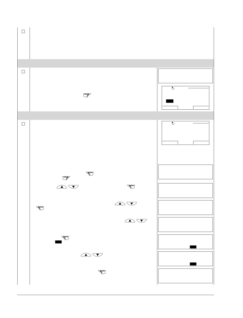
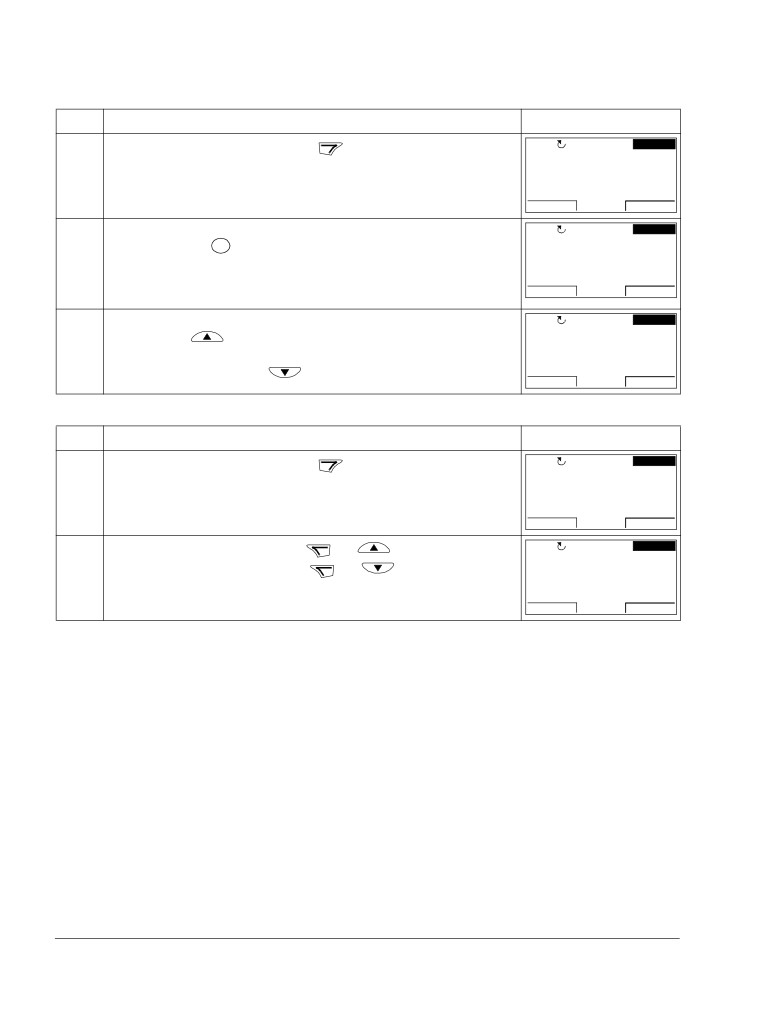
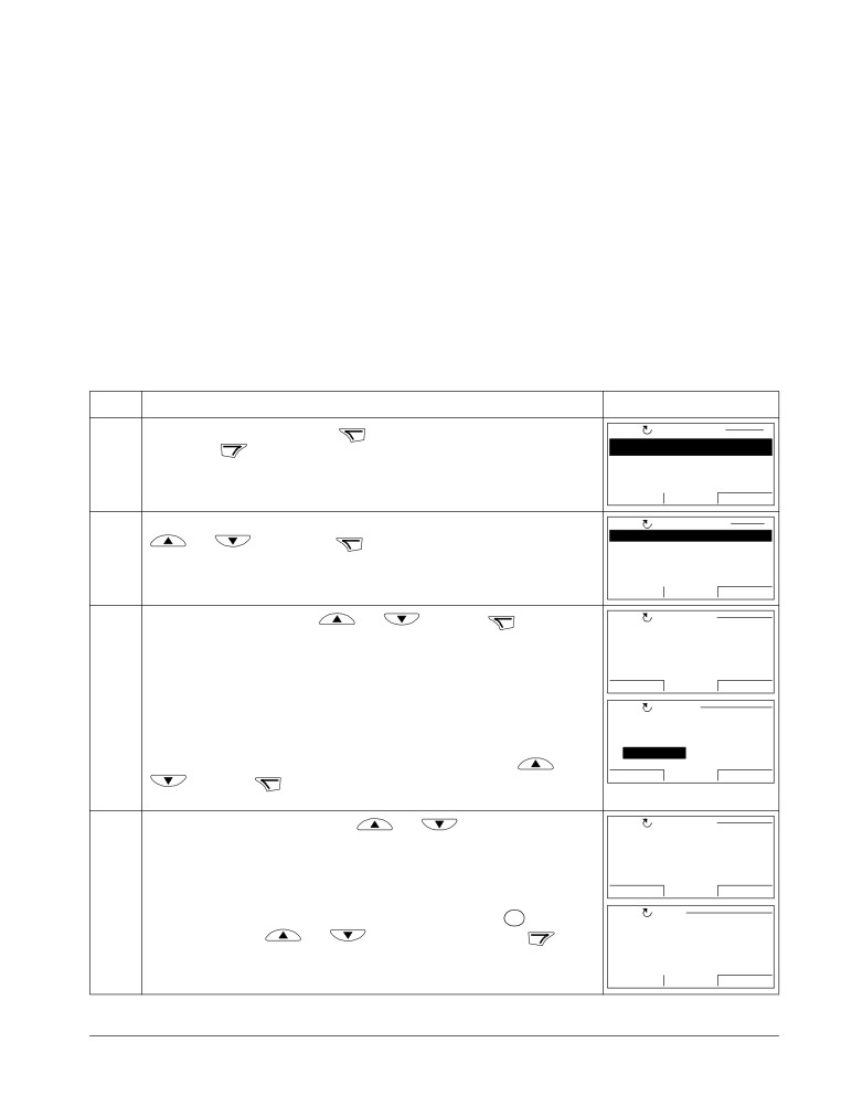
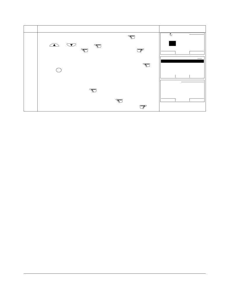
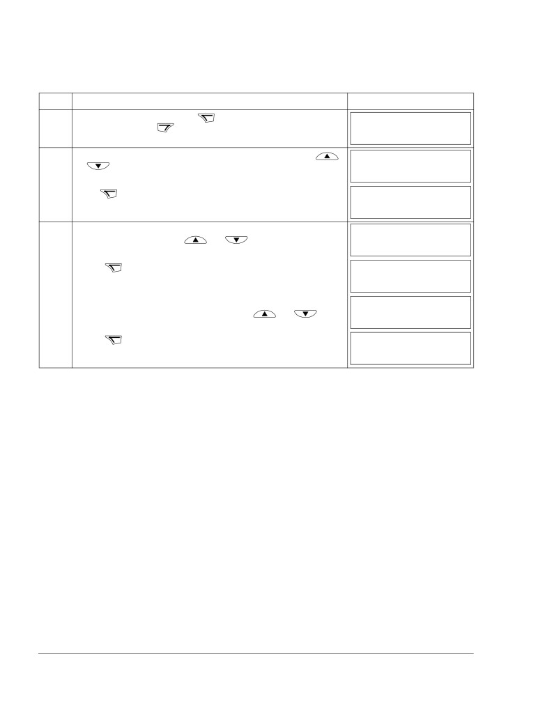
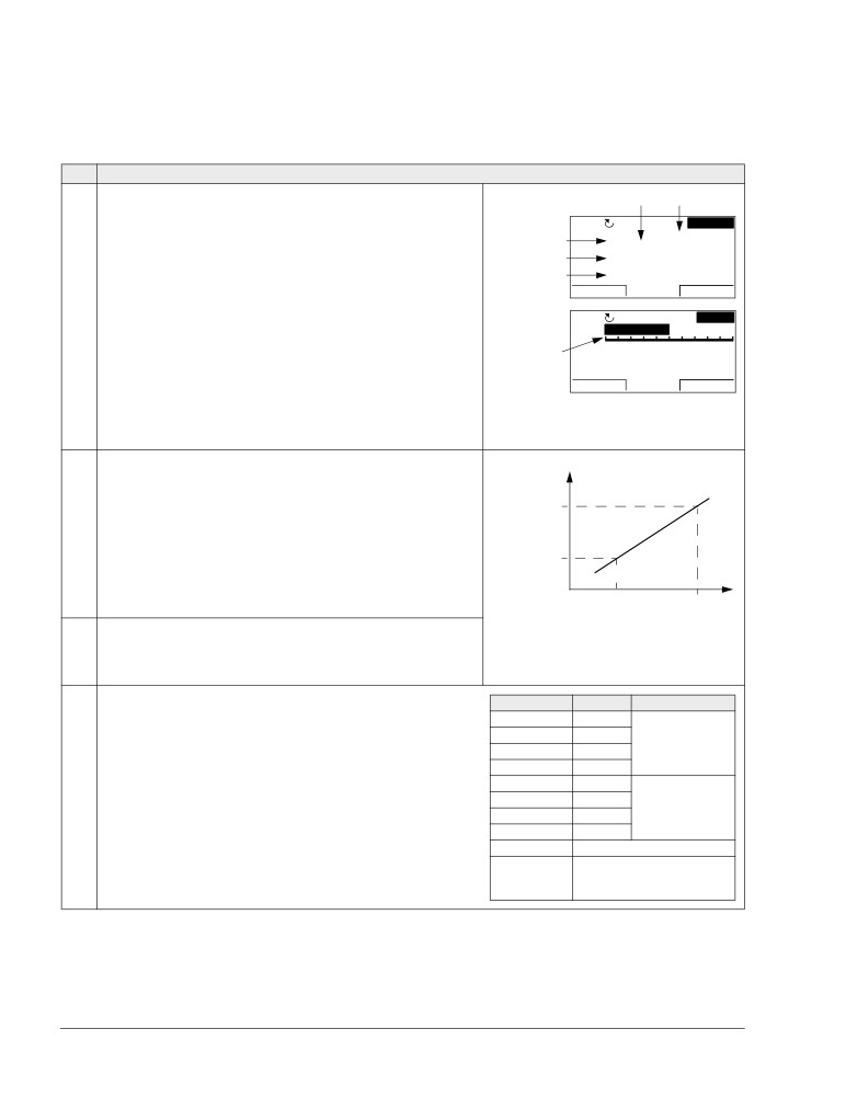
The general parameter setting procedure:
REM
1. To go to the Main menu, press
if the bottom line shows OUTPUT;
rEF
MENU
FWD
otherwise press
repeatedly until you see MENU at the bottom.
2. Press keys
/
until you see “PAr” and press
REM
-01-
PAR
FWD
3. Find the appropriate parameter group with keys
/
and press
REM
2001
PAR
FWD
4. Find the appropriate parameter in the group with keys
/
REM
2002
PAR
FWD
5. Press and hold
for about two seconds until the parameter value is
REM
shown with
SET
under the value.
1500
rpm
PAR
SET
FWD
6. Change the value with keys
/
. The value changes faster while
REM
you keep the key pressed down.
1600
rpm
PAR
SET
FWD
7. Save the parameter value by pressing
REM
2002
PAR
FWD
Start-up, control with I/O and ID Run
ACS550-01/U1 User’s Manual
39
Select the application macro (parameter 9902). The general
REM
parameter setting procedure is given above.
9902
PAR
FWD
The default value 1 (ABB STANDARD) is suitable in most cases.
Select the motor control mode (parameter 9904).
REM
1
(VECTOR:SPEED) is suitable in most cases. 2 (VECTOR:TORQ) is suitable for
9904
PAR
FWD
torque control applications. 3 (SCALAR:FREQ) is recommended
• for multimotor drives when the number of the motors connected to the
drive is variable
• when the nominal current of the motor is less than 20% of the nominal
current of the drive
• when the drive is used for test purposes with no motor connected.
Enter the motor data from the motor nameplate:
Note: Set the motor data to
exactly the same value as on
the motor nameplate. For
ABB Motors
example, if the motor nominal
3
motor
M2AA 200 MLA 4
speed is 1470 rpm on the
IEC 200 M/L 55
No
nameplate, setting the value of
Ins.cl. F
IP 55
parameter 9908 MOTOR NOM
V
Hz
kW
r/min
A
cos
IA/IN
t
E/s
SPEED to 1500 rpm results in the
690 Y
50
30
1475
32.5
0.83
400 D
50
30
1475
56
0.83
wrong operation of the drive.
660 Y
50
30
1470
34
0.83
380 V
380 D
50
30
1470
59
0.83
supply
415 D
50
30
1475
54
0.83
voltage
440 D
60
35
1770
59
0.83
Cat. no
3GAA 202 001 - ADA
6312/C3
6210/C3
180
IEC 34-1
•
motor nominal voltage (parameter 9905)
REM
9905
PAR
FWD
•
motor nominal current (parameter 9906)
REM
9906
Allowed range: 0.2…2.0 · I2hd A
PAR
FWD
•
motor nominal frequency (parameter 9907)
REM
9907
PAR
FWD
•
motor nominal speed (parameter 9908)
REM
9908
PAR
FWD
•
motor nominal power (parameter 9909)
REM
9909
PAR
FWD
Start-up, control with I/O and ID Run
40
ACS550-01/U1 User’s Manual
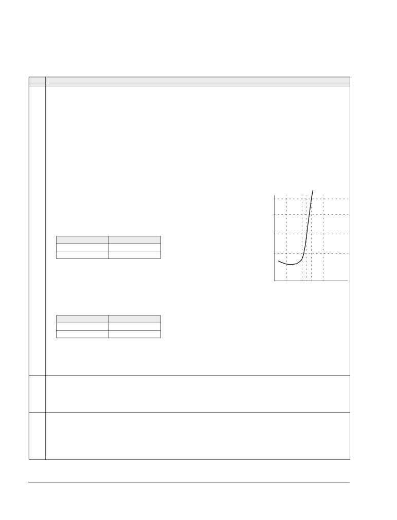
Select the motor identification method (parameter 9910).
The default value 0 (OFF/IDMAGN) using the identification magnetization is suitable for most
applications. It is applied in this basic start-up procedure. Note however that this requires
that:
• parameter 9904 is set to 1 (VECTOR:SPEED) or 2 (VECTOR:TORQ), or
• parameter 9904 is set to 3 (SCALAR:FREQ) and parameter 2101 is set to 3 (SCALAR FLYST)
or 5 (FLY + BOOST).
If your selection is 0 (OFF/IDMAGN), move to the next step.
Value 1 (ON), which performs a separate ID Run, should be selected if:
• vector control mode is used [parameter 9904 = 1 (VECTOR:SPEED) or 2 (VECTOR:TORQ)],
and/or
• the operation point is near zero speed, and/or
• operation at torque range above the motor nominal torque over a wide speed range and
without any measured speed feedback is required.
If you decide to do the ID Run [value 1 (ON)], continue by following the separate instructions
given on page 45 in section How to perform the ID Run and then return to step DIRECTION
OF THE MOTOR ROTATION on page 40.
IDENTIFICATION MAGNETIZATION WITH ID RUN SELECTION 0 (OFF/IDMAGN)
As stated above, the identification magnetization is performed only if:
• parameter 9904 is set to 1 (VECTOR:SPEED) or 2 (VECTOR:TORQ), or
• parameter 9904 is set to 3 (SCALAR:FREQ) and parameter 2101 is set to 3 (SCALAR FLYST)
or 5 (FLY + BOOST).
LOC
Press key
REM
to switch to local control (LOC shown on the left).
Press
to start the drive. The motor model is now calculated by magnetizing the motor
for 10 to 15 s at zero speed (motor not rotating).
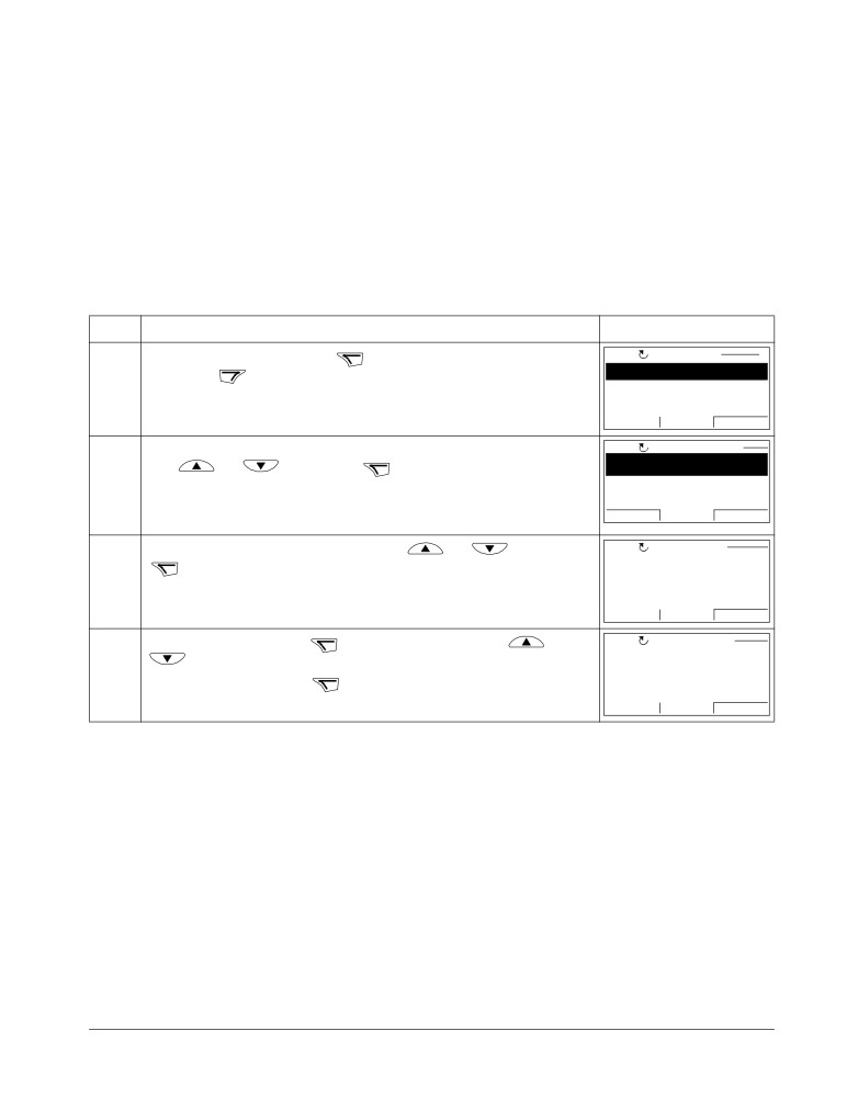
DIRECTION OF THE MOTOR ROTATION
Check the direction of the motor rotation.
• If the drive is in remote control (REM shown on the left),
LOC
LOC
REM
Hz
• To go to the Main menu, press
if the bottom line shows
SET
FWD
OUTPUT; otherwise press
repeatedly until you see
MENU at the bottom.
• Press keys
/
until you see “rEF” and press
• Increase the frequency reference from zero to a small value
with key
• Press
to start the motor.
• Check that the actual direction of the motor is the same as
indicated on the display (FWD means forward and REV
reverse).
• Press
to stop the motor.
Start-up, control with I/O and ID Run
ACS550-01/U1 User’s Manual
41
To change the direction of the motor rotation:
forward
• Disconnect input power from the drive, and wait 5 minutes
direction
for the intermediate circuit capacitors to discharge. Measure
the voltage between each input terminal (U1, V1 and W1)
and earth with a multimeter to ensure that the drive is
reverse
discharged.
direction
• Exchange the position of two motor cable phase conductors
at the drive output terminals or at the motor connection box.
• Verify your work by applying input power and repeating the
check as described above.
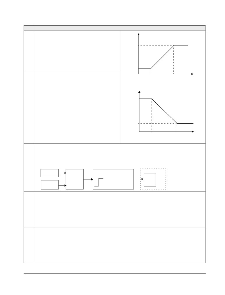
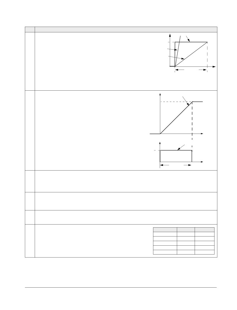
SPEED LIMITS AND ACCELERATION/DECELERATION TIMES
Set the minimum speed (parameter 2001).
LOC
2001
PAR
FWD
Set the maximum speed (parameter 2002).
LOC
2002
PAR
FWD
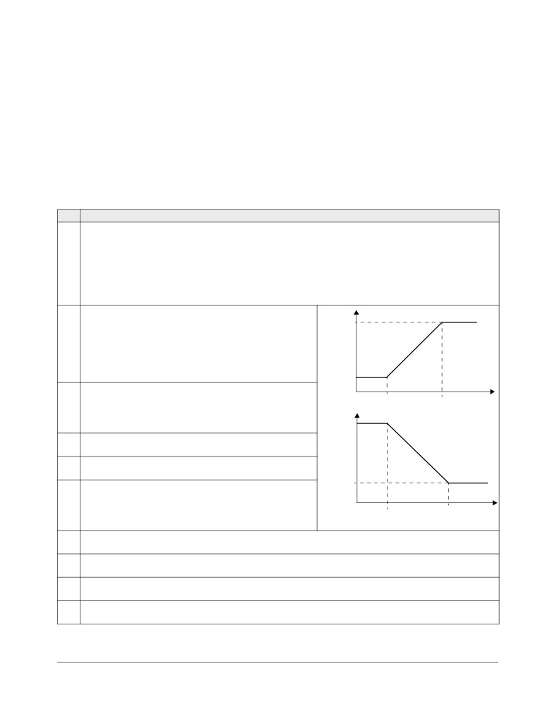
Set the acceleration time 1 (parameter 2202).
LOC
2202
Note: Check also acceleration time 2 (parameter 2205) if two
PAR
FWD
acceleration times will be used in the application.
Set the deceleration time 1 (parameter 2203).
LOC
2203
Note: Set also deceleration time 2 (parameter 2206) if two
PAR
FWD
deceleration times will be used in the application.
SAVING A USER PARAMETER SET AND FINAL CHECK
The start-up is now completed. However, it might be useful at
LOC
this stage to set the parameters required by your application
9902
PAR
FWD
and save the settings as a user parameter set as instructed in
section User parameter sets on page 88.
Check that the drive state is OK.
Basic Control Panel: Check that there are no faults or alarms
shown on the display. If you want to check the LEDs on the
front of the drive, switch first to remote control (otherwise a
fault is generated) before removing the panel and verifying that
the red LED is not lit and the green LED is lit but not blinking.
Assistant Control Panel: Check that there are no faults or
alarms shown on the display and that the panel LED is green
and does not blink.
The drive is now ready for use.
Start-up, control with I/O and ID Run
42
ACS550-01/U1 User’s Manual
How to perform the guided start-up
To be able to perform the guided start-up, you need the Assistant Control Panel.
Before you start, ensure that you have the motor nameplate data on hand.
SAFETY
The start-up may only be carried out by a qualified electrician.
The safety instructions given in chapter Safety instructions must be followed during
the start-up procedure.
The drive will start up automatically at power up, if the external run command is on.
Check the installation. See the checklist in chapter Installation, page 35.
Check that the starting of the motor does not cause any danger.
De-couple the driven machine if:
• there is a risk of damage in case of incorrect direction of rotation, or
• an ID Run needs to be performed during the drive start-up. ID Run is essential only in
applications that require the ultimate in motor control accuracy.
POWER-UP
Apply input power. The control panel first asks if you want to use
REM CHOICE
Do you want to
the Start-up Assistant.
use the start-up
OK
assistant?
• Press
(when
Yes
is highlighted) to run the Start-up
Yes
No
Assistant.
EXIT
00:00
OK
EXIT
• Press
if you do not want to run the Start-up Assistant.
OK
• Press key
to highlight
No
and then press
if you want to
REM CHOICE
Show start-up
make the panel ask (or not ask) the question about running the
assistant on
next boot?
Start-up Assistant again the next time you switch on the power to
Yes
the drive.
No
EXIT
00:00
OK
SELECTING THE LANGUAGE
If you decided to run the Start-up Assistant, the display then asks
REM
PAR EDIT
you to select the language. Scroll to the desired language with
9901 LANGUAGE
SAVE
keys
/
and press
to accept.
ENGLISH
EXIT
[0]
If you press
, the Start-up Assistant is stopped.
EXIT
00:00
SAVE
STARTING THE GUIDED SET-UP
The Start-up Assistant now guides you through the set-up tasks,
REM
PAR EDIT
starting with the motor set-up. Set the motor data to exactly the
9905 MOTOR NOM VOLT
same value as on the motor nameplate.
220 V
Scroll to the desired parameter value with keys
/
and
EXIT
00:00
SAVE
SAVE
press
to accept and continue with the Start-up Assistant.
EXIT
Note: At any time, if you press
, the Start-up Assistant is
stopped and the display goes to the Output mode.
Start-up, control with I/O and ID Run
ACS550-01/U1 User’s Manual
43
After completing a set-up task, the Start-up Assistant suggests the
REM CHOICE
Do you want to
next one.
continue with
OK
application setup?
• Press
(when
Continue
is highlighted) to continue with the
Continue
Skip
suggested task.
EXIT
00:00
OK
OK
• Press key
to highlight
Skip
and then press
to move to
the following task without doing the suggested task.
EXIT
• Press
to stop the Start-up Assistant.
SAVING A USER PARAMETER SET AND FINAL CHECK
The start-up is now completed. However, it might be useful at this
stage to set the parameters required by your application and save
the settings as a user parameter set as instructed in section User
parameter sets on page 88.
After the whole set-up is completed, check there are no faults or
alarms shown on the display and the panel LED is green and does
not blink.
The drive is now ready for use.
Start-up, control with I/O and ID Run
44
ACS550-01/U1 User’s Manual
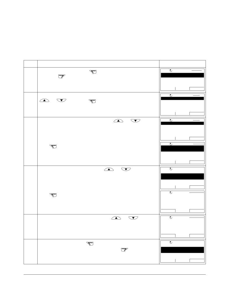
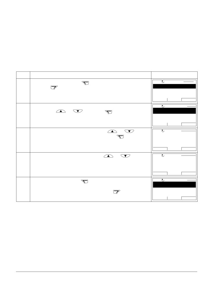
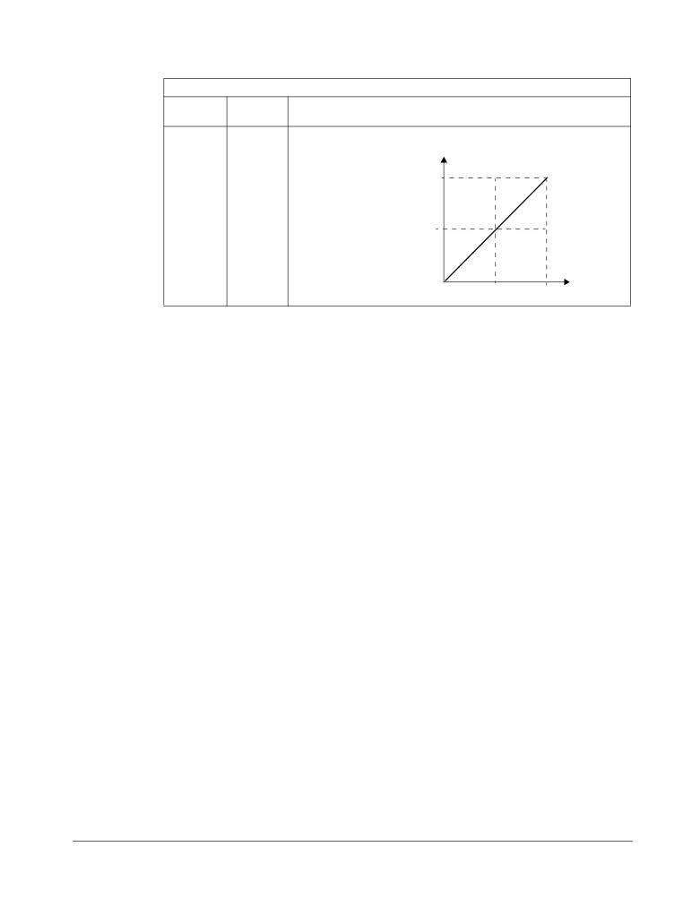
How to control the drive through the I/O interface
The table below instructs how to operate the drive through the digital and analog
inputs when:
• the motor start-up is performed, and
• the default (standard) parameter settings are valid.
Displays of the Basic Control Panel are shown as an example.
PRELIMINARY SETTINGS
If you need to change the direction of rotation, check that parameter
1003 is set to 3 (REQUEST).
Ensure that the control connections are wired according to the
See section ABB Standard
macro on page 78.
connection diagram given for the ABB Standard macro.
Ensure that the drive is in remote control. Press key
to switch
In remote control, the panel
LOC
REM
display shows text REM.
between remote and local control.
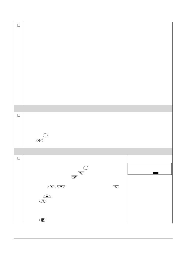
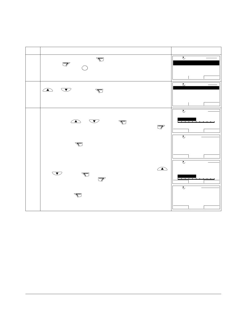
STARTING AND CONTROLLING THE SPEED OF THE MOTOR
Start by switching digital input DI1 on.
REM
Hz
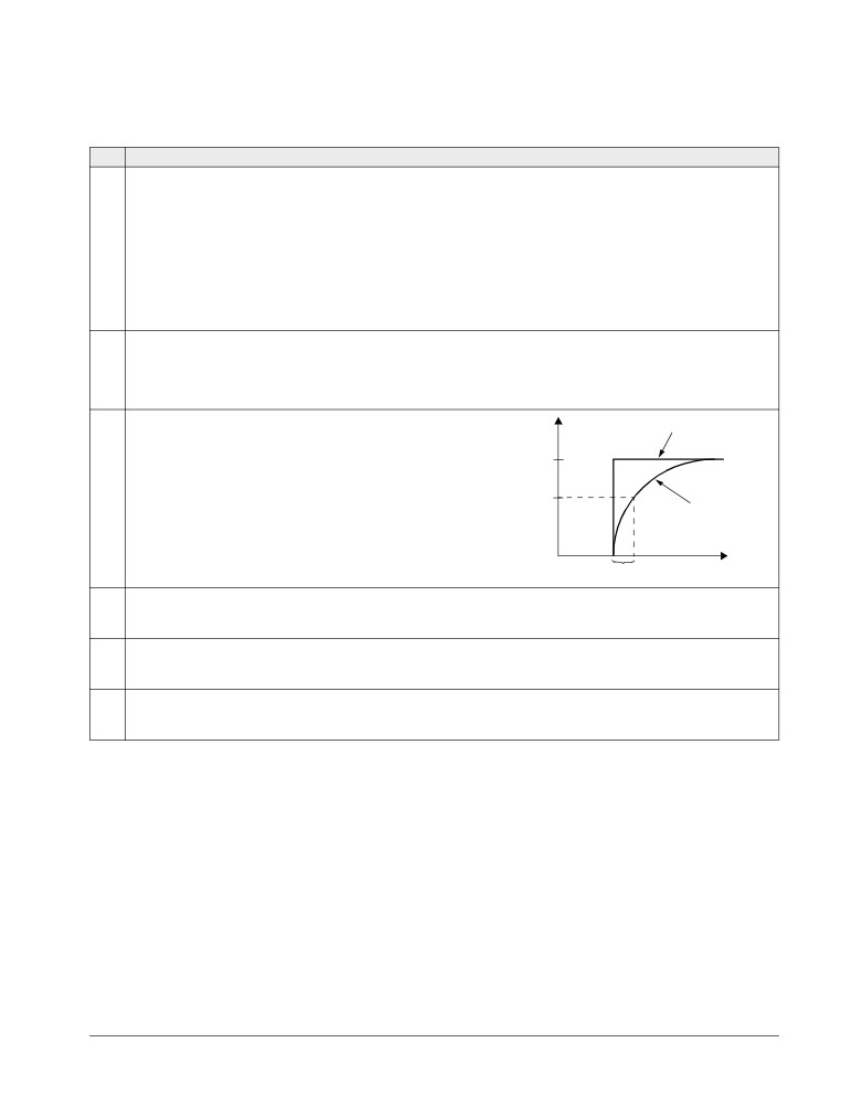
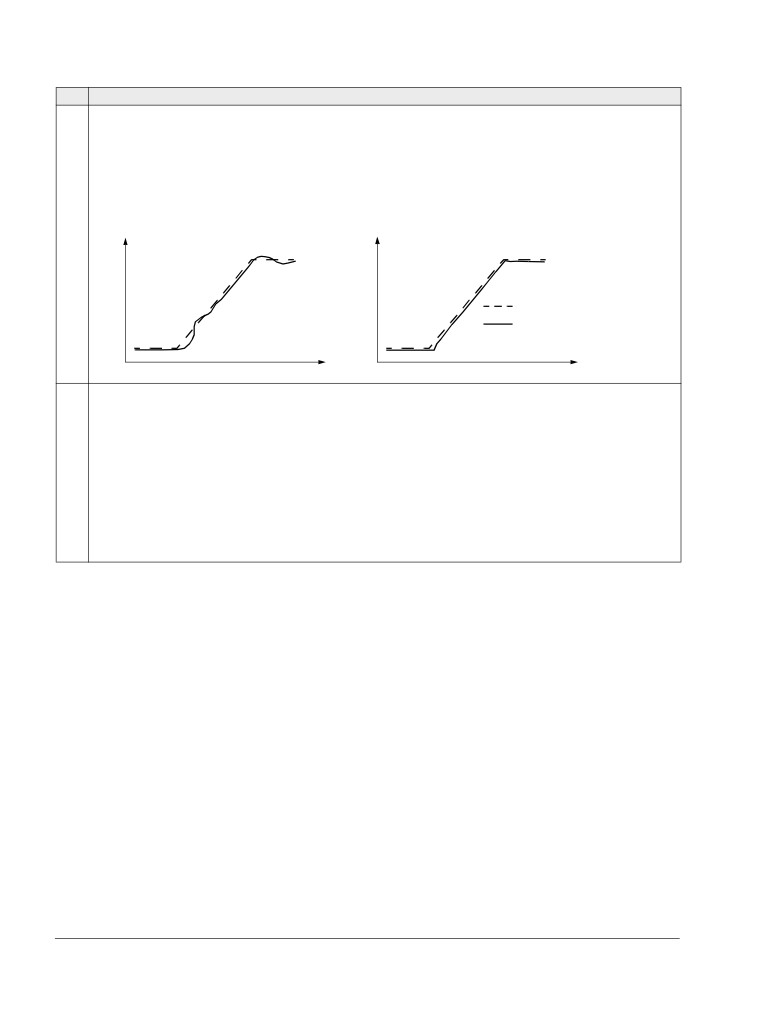
Assistant Control Panel: The arrow starts rotating. It is dotted until the
OUTPUT
FWD
setpoint is reached.
Basic Control Panel: Text FWD starts flashing fast and stops after the
setpoint is reached
Regulate the drive output frequency (motor speed) by adjusting the
REM
Hz
voltage of analog input AI1.
OUTPUT
FWD
CHANGING THE DIRECTION OF ROTATION OF THE MOTOR
Reverse direction: Switch digital input DI2 on.
REM
Hz
OUTPUT
REV
Forward direction: Switch digital input DI2 off.
REM
Hz
OUTPUT
FWD
STOPPING THE MOTOR
Switch digital input DI1 off. The motor stops.
REM
Hz
Assistant Control Panel: The arrow stops rotating.
OUTPUT
FWD
Basic Control Panel: Text FWD starts flashing slowly.
Start-up, control with I/O and ID Run
ACS550-01/U1 User’s Manual
45
How to perform the ID Run
The drive estimates motor characteristics automatically using identification
magnetization when the drive is started for the first time and after any motor
parameter (Group 99: START-UP DATA) is changed. This is valid when parameter
9910 ID RUN has value 0 (OFF/IDMAGN), and
• parameter 9904 = 1 (VECTOR:SPEED) or 2 (VECTOR:TORQ), or
• parameter 9904 = 3 (SCALAR:FREQ) and parameter 2101 = 3 (SCALAR FLYST) or
5
(FLY + BOOST).
In most applications there is no need to perform a separate ID Run [9910 ID RUN =
1
(ON)]. The ID Run should be selected if:
• vector control mode is used [parameter 9904 = 1 (VECTOR:SPEED) or
2
(VECTOR:TORQ)], and/or
• the operation point is near zero speed, and/or
• operation at torque range above the motor nominal torque over a wide speed
range and without any measured speed feedback is required.
Note: If motor parameters (Group 99: START-UP DATA) are changed after the ID
Run, it must be repeated.
ID Run procedure
The general parameter setting procedure is not repeated here. For Assistant Control
Panel see page 55 and for Basic Control Panel page 73 in chapter Control panels.
PRE-CHECK
WARNING! The motor will run at up to approximately 50…80% of the nominal speed
during the ID Run. The motor will rotate in the forward direction. Ensure that it is
safe to run the motor before performing the ID Run!
De-couple the motor from the driven equipment.
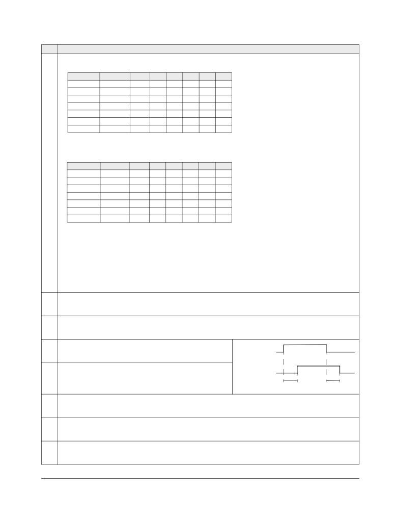
Check that the values of the motor data parameters 9905…9909 are equivalent to those on
the motor nameplate, as shown in the steps on page 39.
If parameter values (Group 01: OPERATING DATA to Group 98: OPTIONS) are changed
before the ID Run, check that the new settings meet the following conditions:
2001 MINIMUM SPEED < 0 rpm
2002 MAXIMUM SPEED > 80% of the motor rated speed
2003 MAXIMUM CURRENT > I2hd
2017 MAX TORQUE 1 > 50% or 2018 MAX TORQUE 2 > 50%, depending on which limit is in
use according to parameter 2014 MAX TORQUE SEL.
Check that the Run Enable signal is on (parameter 1601).
LOC
Ensure that the panel is in local control (LOC shown on the left / at the top). Press key
to
REM
switch between local and remote control.
Start-up, control with I/O and ID Run
46
ACS550-01/U1 User’s Manual
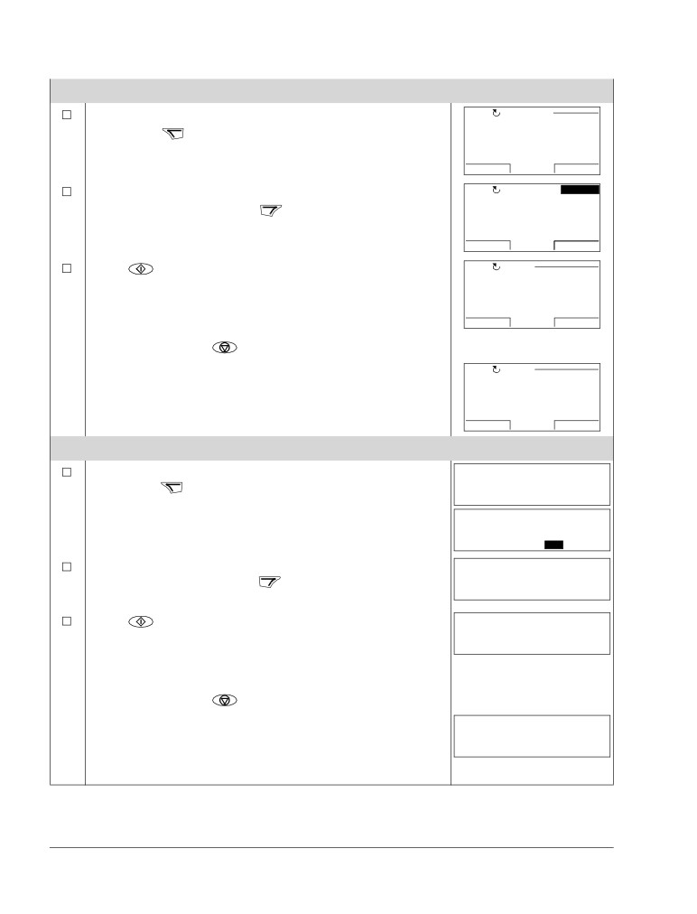
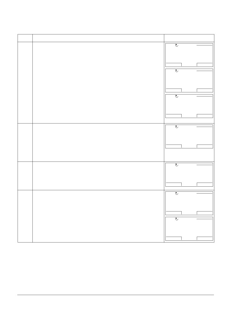
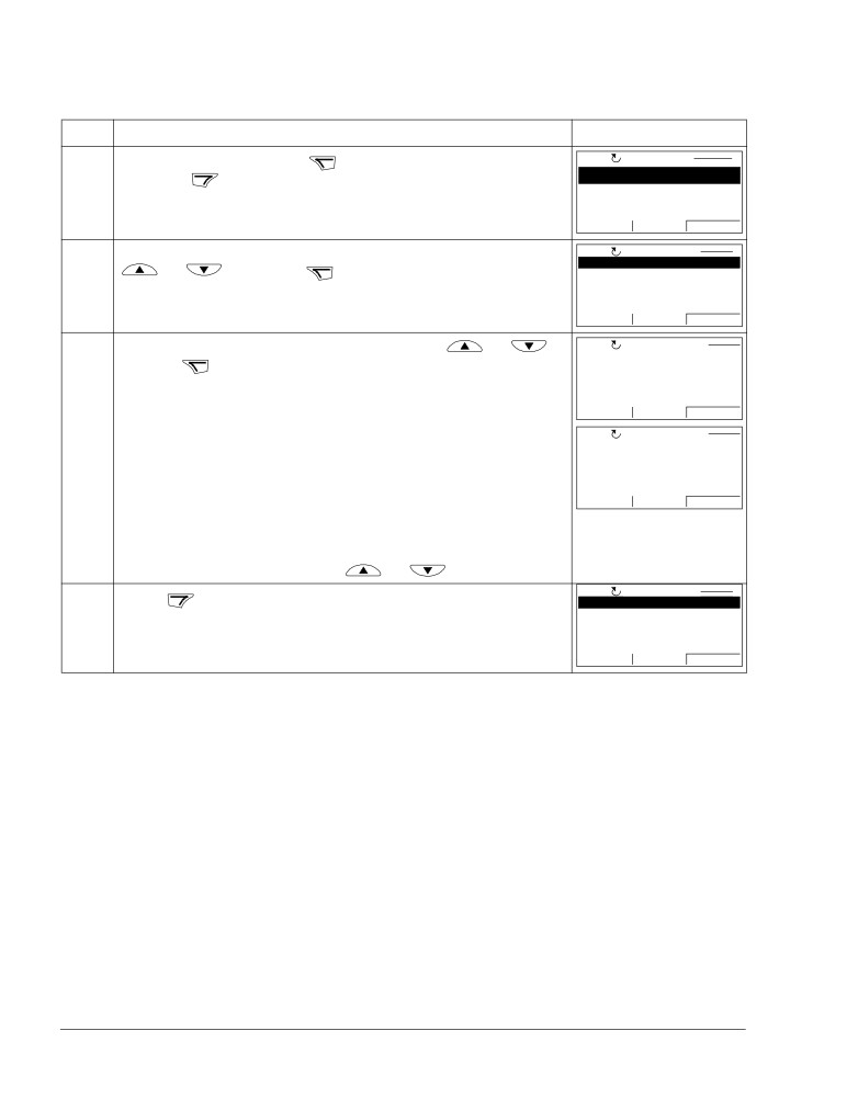
ID RUN WITH THE ASSISTANT CONTROL PANEL
Change parameter 9910 ID RUN to 1 (ON). Save the new setting
LOC
PAR EDIT
SAVE
by pressing
9910 ID RUN
ON
[1]
CANCEL
00:00
SAVE
If you want to monitor actual values during the ID Run, go to
LOC
50.0Hz
EXIT
the Output mode by pressing
repeatedly until you get
0.0 Hz
there.
0.0 A
0.0 %
DIR
00:00
MENU
Press
to start the ID Run. The panel keeps switching
LOC ALARM
between the display that was shown when you started the ID
ALARM 2019
Run and the alarm display presented on the right.
ID run
In general, it is recommended not to press any control panel
00:00
keys during the ID Run. However, you can stop the ID Run at
any time by pressing
After the ID Run is completed, the alarm display is not shown
LOC FAULT
any more.
FAULT 11
If the ID Run fails, the fault display presented on the right is
ID RUN FAIL
shown.
00:00
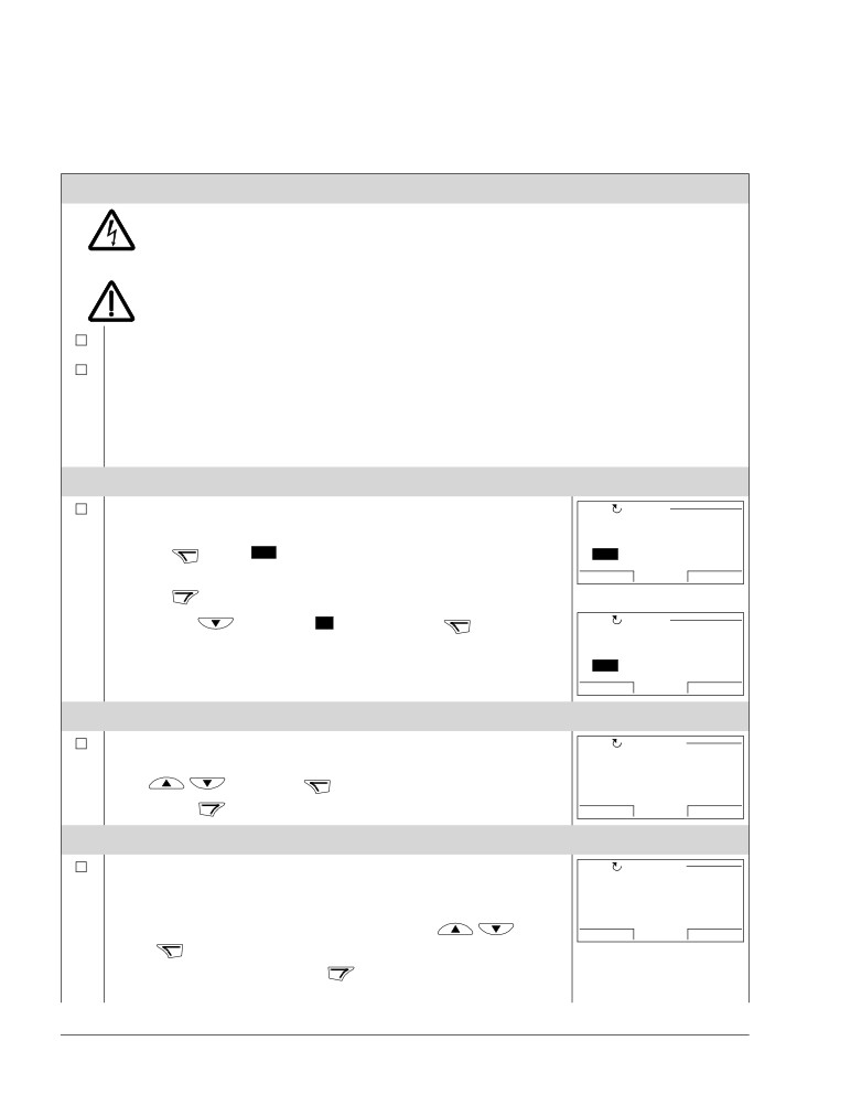
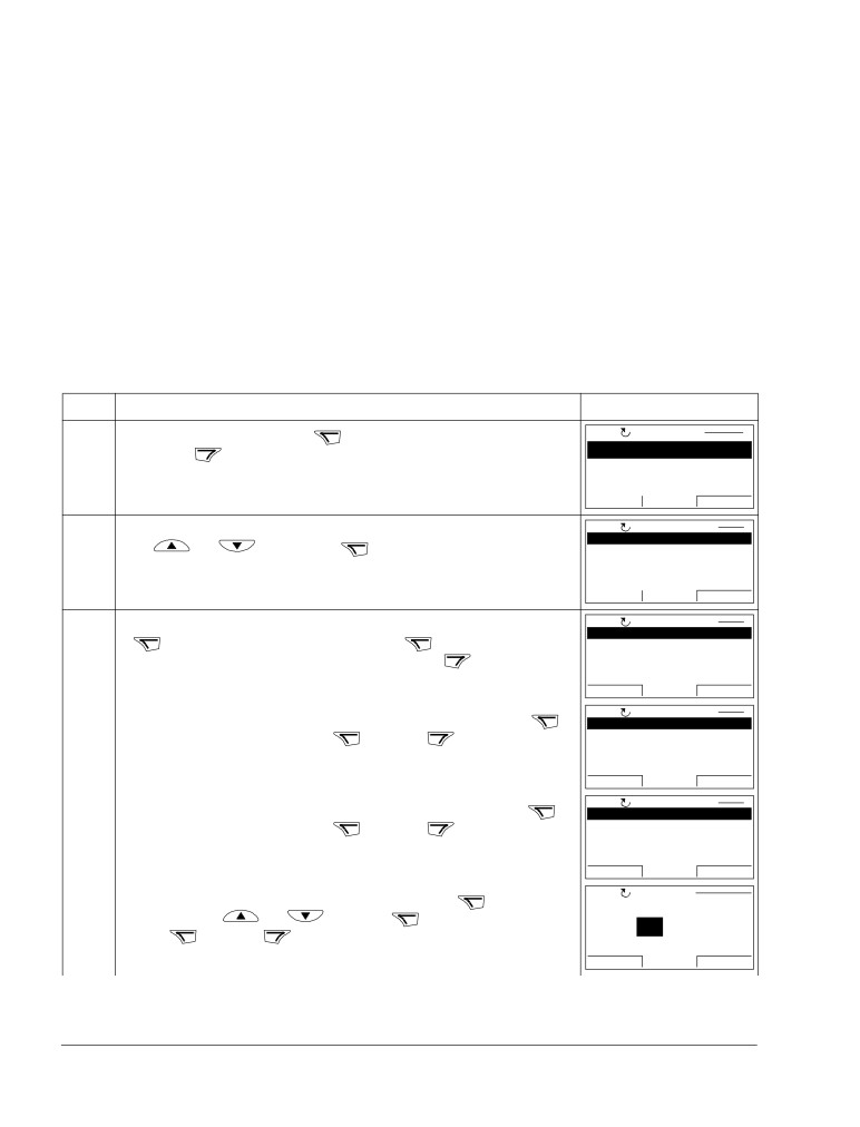
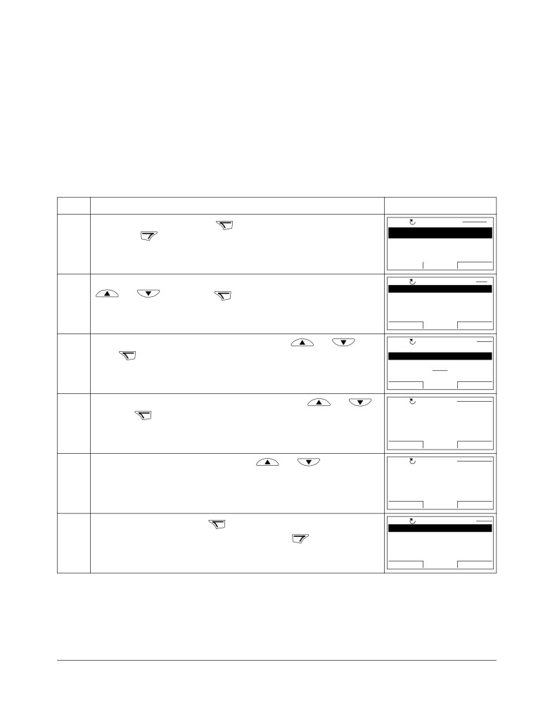
ID RUN WITH THE BASIC CONTROL PANEL
Change parameter 9910 ID RUN to 1 (ON). Save the new setting
LOC
by pressing
9910
PAR
FWD
LOC
1
PAR
SET
FWD
If you want to monitor actual values during the ID Run, go to
LOC
Hz
the Output mode by pressing
repeatedly until you get
OUTPUT
FWD
there.
Press
to start the ID Run. The panel keeps switching
LOC
between the display that was shown when you started the ID
A2019
FWD
Run and the alarm display presented on the right.
In general, it is recommended not to press any control panel
keys during the ID Run. However, you can stop the ID Run at
any time by pressing
After the ID Run is completed, the alarm display is not shown
LOC
any more.
F0011
FWD
If the ID Run fails, the fault display presented on the right is
shown.
Start-up, control with I/O and ID Run
ACS550-01/U1 User’s Manual
47
Control panels
About control panels
Use a control panel to control the drive, read status data and adjust parameters. The
drive works with either of two different control panel types:
• Basic Control Panel - This panel (described in section Basic Control Panel on
page 68) provides basic tools for manual entry of parameter values.
• Assistant Control Panel - This panel (described below) includes pre-programmed
assistants to automate the most common parameter setups. The panel provides
language support. It is available with different language sets.
Compatibility
The manual is compatible with the following panel versions:
• Basic Control Panel: ACS-CP-C Rev. M or later
• Assistant Control Panel (Area 1): ACS-CP-A Rev. F or later
(new panel series manufactured since 2007 with serial number XYYWWRXXXX,
where year YY = 07 or greater and revision R = F, G, E, …)
• Assistant Control Panel (Asia): ACS-CP-D Rev. Q or later
See page 51 for how to find out the version of your Assistant Control Panel. See
parameter 9901 LANGUAGE to see the languages supported by the different Assistant
Control Panels.
Control panels
48
ACS550-01/U1 User’s Manual
Assistant Control Panel
Features
The Assistant Control Panel features:
• alphanumeric control panel with an LCD display
• language selection for the display
• Start-up Assistant to ease drive commissioning
• copy function - parameters can be copied to the control panel memory for later
transfer to other drives or for backup of a particular system.
• context sensitive help
• real time clock.
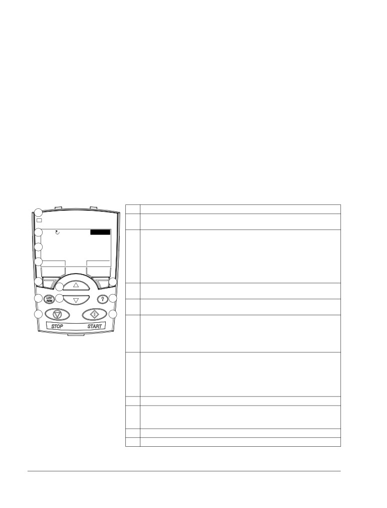
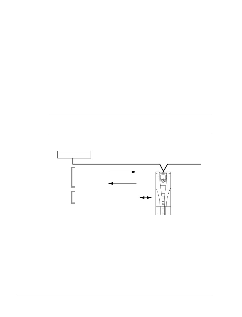
Overview
The following table summarizes the key functions and displays on the Assistant
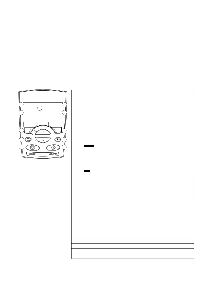
Control Panel.
No.
Use
1
1
Status LED - Green for normal operation. If LED is flashing, or red, see
section Diagnostic displays on page 259.
2a
LOC
49.1Hz
2
LCD display - Divided into three main areas:
49.1 Hz
a. Status line - variable, depending on the mode of operation, see section
2b
0.5 A
Status line on page 49.
10.7 %
b. Center - variable; in general, shows signal and parameter values, menus or
2c
DIR
00:00
MENU
lists. Shows also faults and alarms.
c. Bottom line - shows current functions of the two soft keys and, if enabled,
the clock display.
3
4
5
3
Soft key 1 - Function depends on the context. The text in the lower left corner
of the LCD display indicates the function.
7
6
8
4
Soft key 2 - Function depends on the context. The text in the lower right
corner of the LCD display indicates the function.
9
10
5
Up -
• Scrolls up through a menu or list displayed in the center of the LCD display.
• Increments a value if a parameter is selected.
• Increments the reference value if the upper right corner is highlighted.
Holding the key down changes the value faster.
6
Down -
• Scrolls down through a menu or list displayed in the center of the LCD
display.
• Decrements a value if a parameter is selected.
• Decrements the reference value if the upper right corner is highlighted.
Holding the key down changes the value faster.
7
LOC/REM - Changes between local and remote control of the drive.
8
Help - Displays context sensitive information when the key is pressed. The
information displayed describes the item currently highlighted in the center of
the display.
9
STOP - Stops the drive in local control.
10
START - Starts the drive in local control.
Control panels
ACS550-01/U1 User’s Manual
49
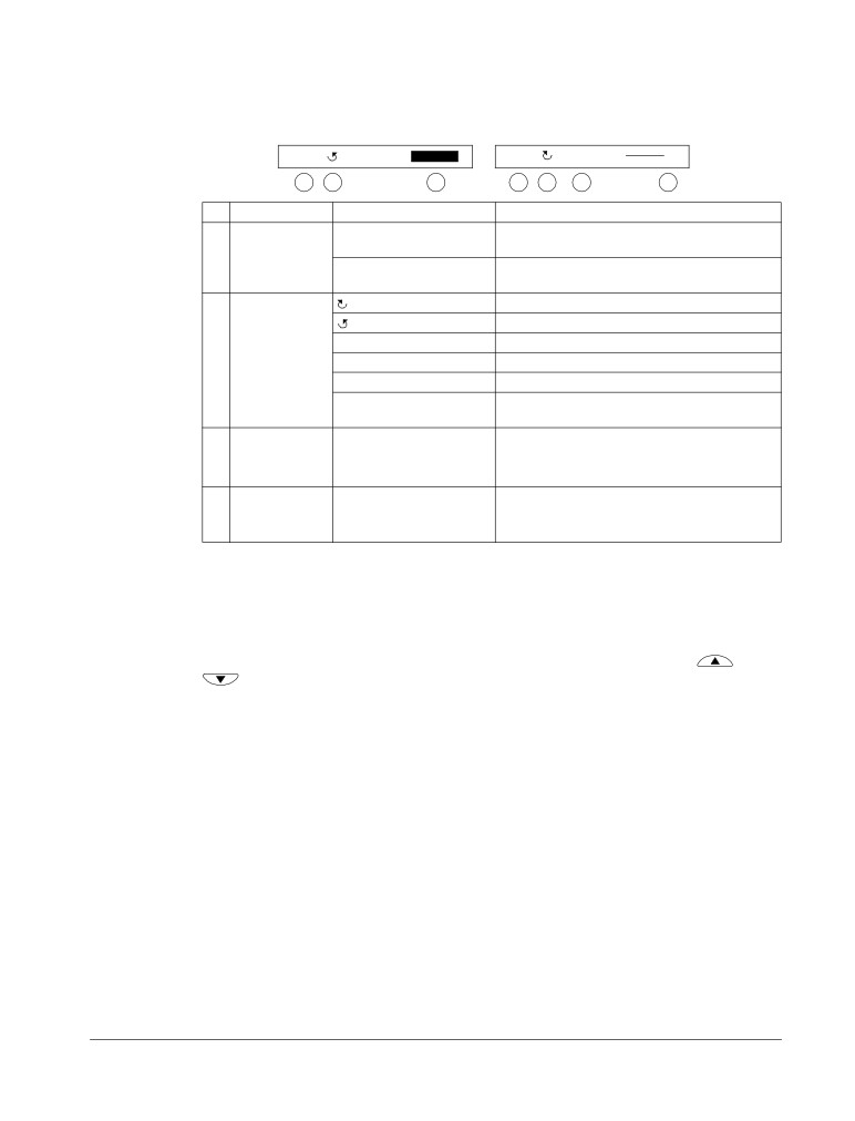
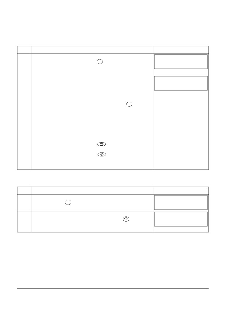
Status line
The top line of the LCD display shows the basic status information of the drive.
LOC
49.1Hz
LOC MAIN MENU
1
1
2
4
1
2
3
4
No.
Field
Alternatives
Significance
1
Control location
LOC
Drive control is local, that is, from the control
panel.
REM
Drive control is remote, such as the drive I/O or
fieldbus.
2
State
Forward shaft direction
Reverse shaft direction
Rotating arrow
Drive is running at setpoint.
Dotted rotating arrow
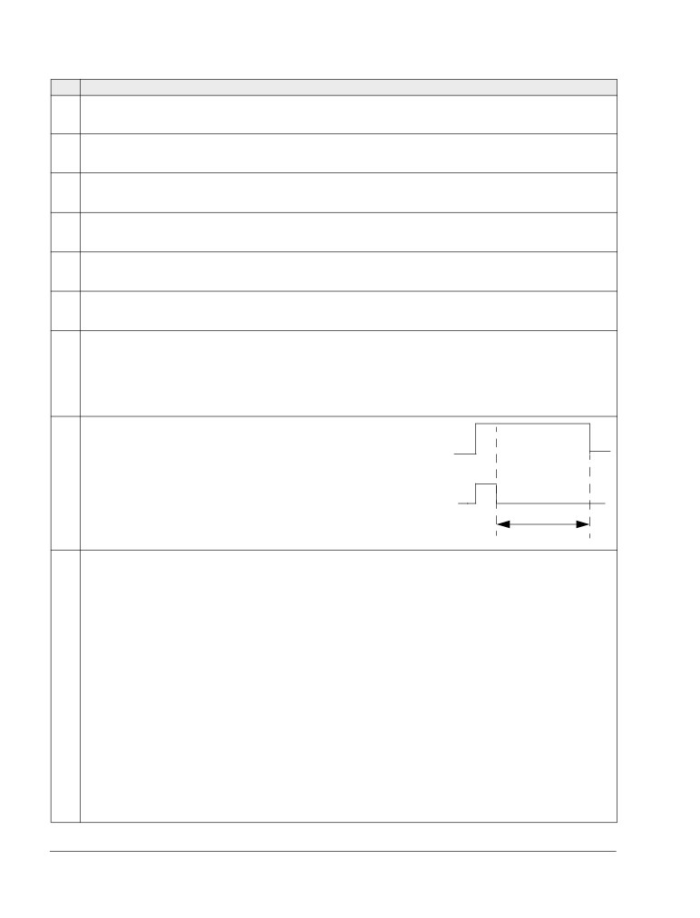
Drive is running but not at setpoint.
Stationary arrow
Drive is stopped.
Dotted stationary arrow
Start command is present, but the motor is not
running, e.g. because start enable is missing.
3
Panel operation
• Name of the current mode
mode
• Name of the list or menu shown
• Name of the operation state, e.g. PAR EDIT.
4
Reference value
• Reference value in the Output mode
or number of the
• Number of the highlighted item, e.g mode,
selected item
parameter group or fault.
Operation
You operate the control panel with menus and keys. The keys include two context-
sensitive soft keys, whose current function is indicated by the text shown in the
display above each key.
You select an option, e.g. operation mode or parameter, by scrolling the
and
arrow keys until the option is highlighted (in reverse video) and then pressing
the relevant soft key. With the right soft key you usually enter a mode, accept an
option or save the changes. The left soft key is used to cancel the made changes
and return to the previous operation level.
The Assistant Control Panel has nine panel modes: Output, Parameters, Assistants,
Changed Parameters, Fault Logger, Time and Date, Parameter Backup, I/O Settings
and Fault. The operation in the first eight modes is described in this chapter. When a
fault or alarm occurs, the panel goes automatically to the Fault mode showing the
fault or alarm. You can reset it in the Output or Fault mode (see chapter
Diagnostics).
Control panels
50
ACS550-01/U1 User’s Manual
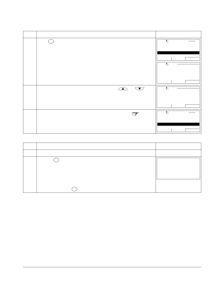
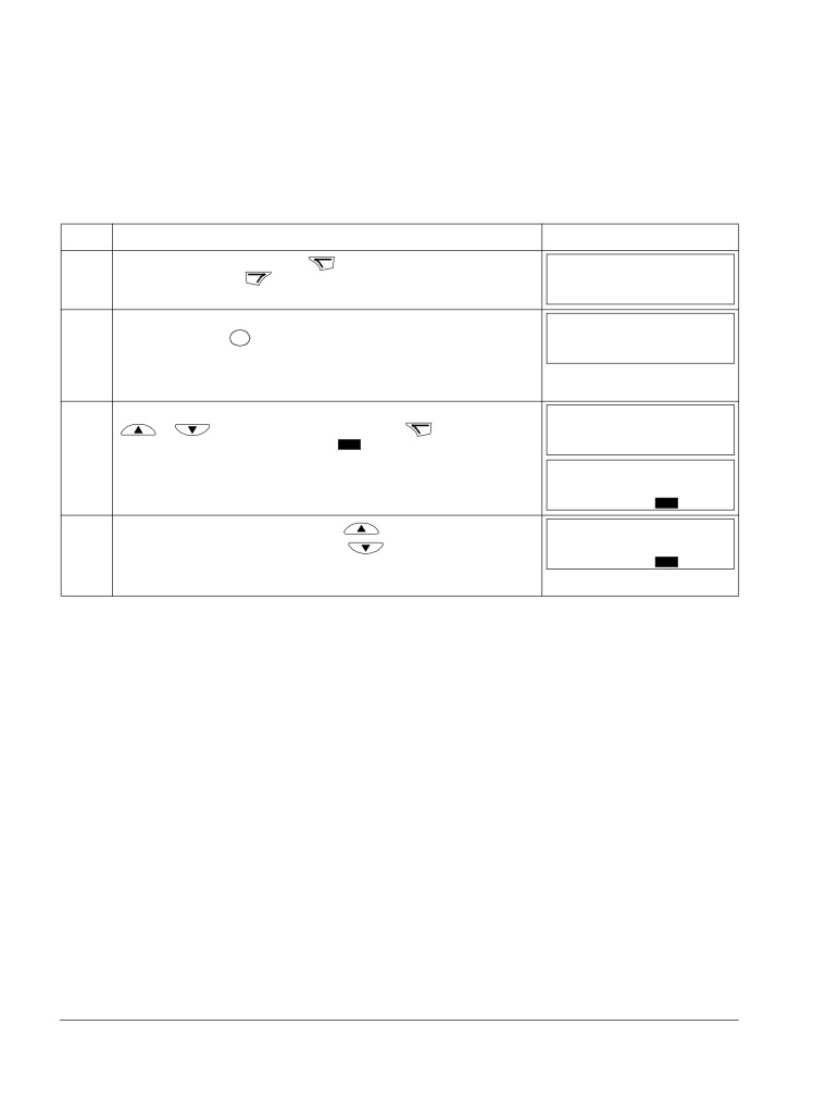
Initially, the panel is in the Output mode, where you can
LOC
49.1Hz
start, stop, change the direction, switch between local and
49.1 Hz
remote control, modify the reference value and monitor up
0.5 A
to three actual values. To do other tasks, go first to the
10.7 %
Main menu and select the appropriate mode on the menu.
DIR
00:00
MENU
The status line (see section Status line on page 49) shows
LOC MAIN MENU
1
the name of the current menu, mode, item or state.
PARAMETERS
ASSISTANTS
CHANGED PAR
EXIT
00:00
ENTER
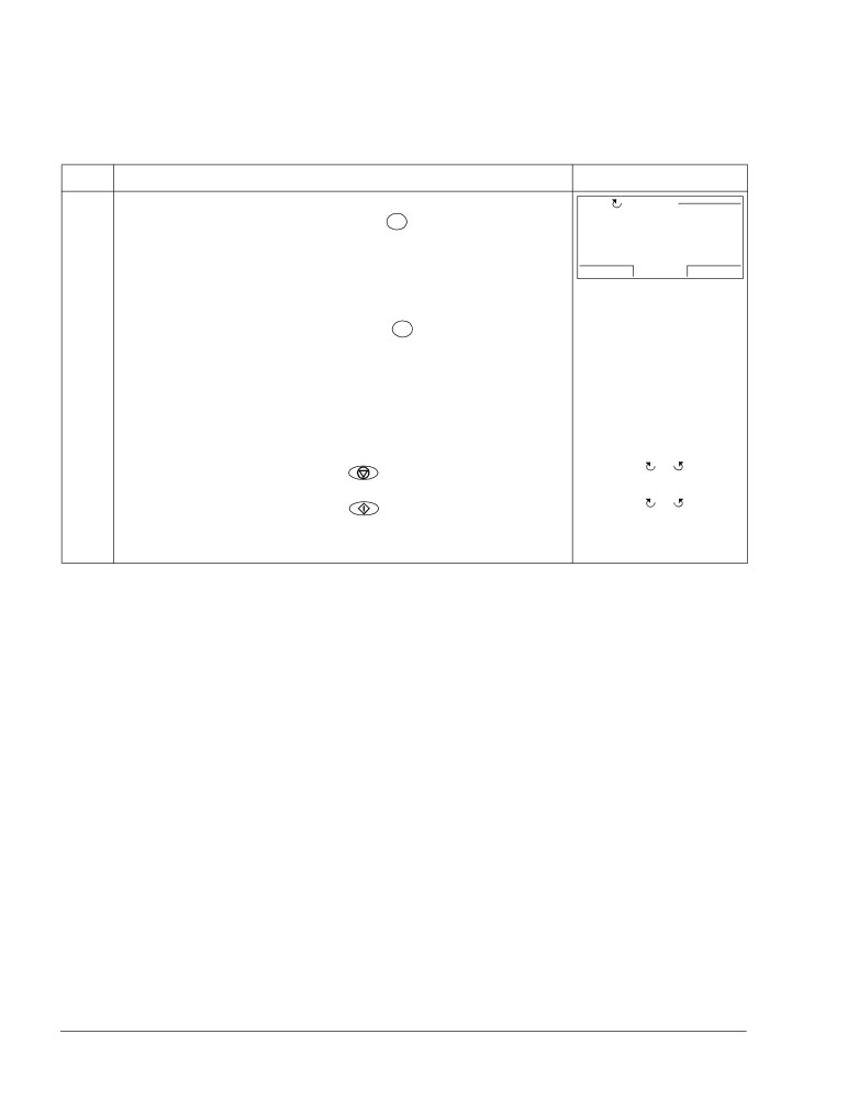
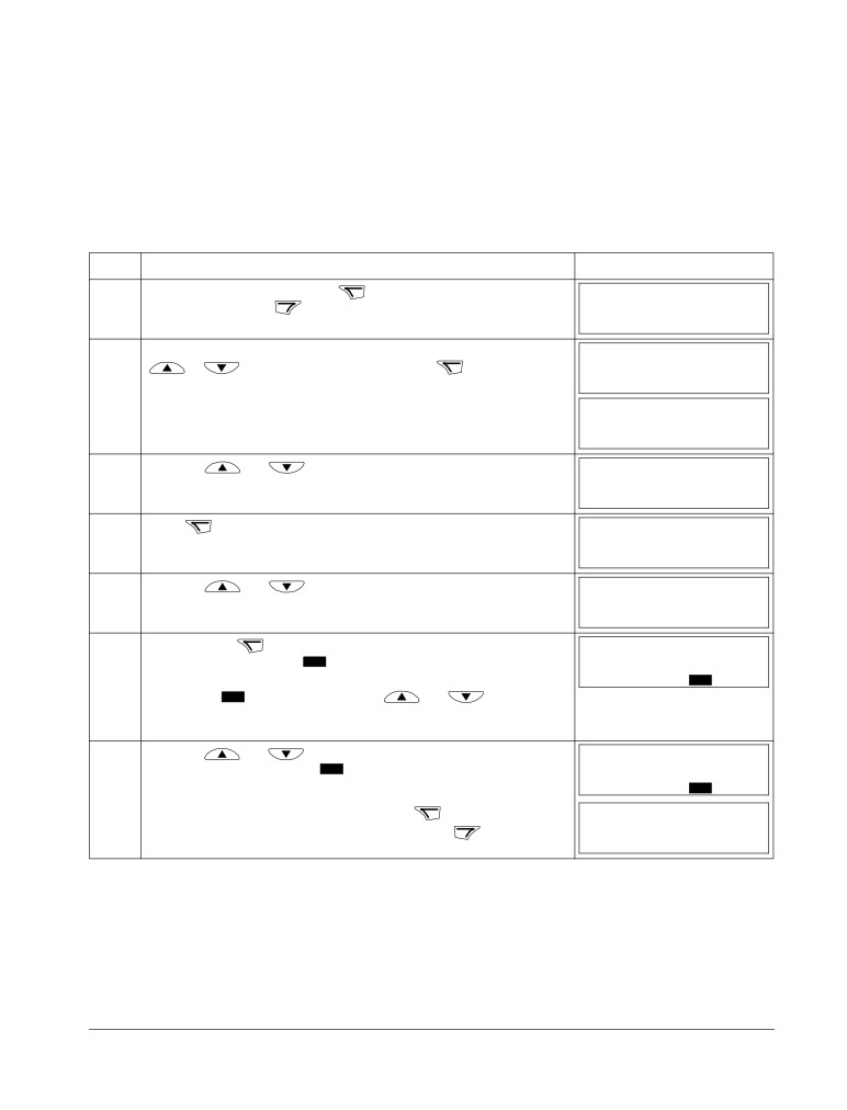
How to do common tasks
The table below lists common tasks, the mode in which you can perform them and
the page number where the steps to do the task are described in detail.
Task
Mode
Page
How to get help
Any
51
How to find out the panel version
At power up
51
How to adjust the display contrast
Output
54
How to switch between local and remote control
Any
52
How to start and stop the drive
Any
52
How to change the direction of the motor rotation
Output
53
How to set the speed, frequency or torque reference
Output
54
How to change the value of a parameter
Parameters
55
How to select the monitored signals
Parameters
56
How to do guided tasks (specification of related parameter sets)
Assistants
57
with assistants
How to view and edit changed parameters
Changed Parameters
60
How to view faults
Fault Logger
61
How to reset faults and alarms
Output, Fault
265
How to show/hide the clock, change date and time formats, set the
Time and Date
62
clock and enable/disable automatic clock transitions according to
the daylight saving changes
How to copy parameters from the drive to the control panel
Parameter Backup
65
How to restore parameters from the control panel to the drive
Parameter Backup
65
How to view backup information
Parameter Backup
66
How to edit and change parameter settings related to I/O terminals
I/O Settings
67
Control panels
ACS550-01/U1 User’s Manual
51
How to get help
Step
Action
Display
1.
Press
?
to read the context-sensitive help text for the item that is highlighted.
LOC
PAR GROUPS
10
01 OPERATING DATA
03 FB ACTUAL SIGNALS
04 FAULT HISTORY
10 START/STOP/DIR
11 REFERENCE SELECT
EXIT
00:00
SEL
LOC HELP
If help text exists for the item, it is shown on the display.
This group defines
external sources
(EXT1 and EXT2) for
commands that enable
start, stop and
EXIT
00:00
2.
If the whole text is not visible, scroll the lines with keys
and
LOC HELP
external sources
(EXT1 and EXT2) for
commands that enable
start, stop and
direction changes.
EXIT
00:00
EXIT
3.
After reading the text, return to the previous display by pressing
LOC
PAR GROUPS
10
01 OPERATING DATA
03 FB ACTUAL SIGNALS
04 FAULT HISTORY
10 START/STOP/DIR
11 REFERENCE SELECT
EXIT
00:00
SEL
How to find out the panel version
Step
Action
Display
1.
If the power is switched on, switch it off.
2.
Keep key
?
pressed down while you switch on the power and read the
PANEL VERSION INFO
Panel FW:
x.xx
information. The display shows the following panel information:
ROM CRC: xxxxxxxxxx
Flash Rev:
x.xx
Panel FW: panel firmware version
xxxxxxxxxxxxxxxxxxxxx
ROM CRC: panel ROM check sum
Flash Rev: flash content version
Flash content comment.
When you release the
key, the panel goes to the Output mode.
?
Control panels
52
ACS550-01/U1 User’s Manual
How to start, stop and switch between local and remote control
You can start, stop and switch between local and remote control in any mode. To be
able to start or stop the drive, the drive must be in local control.
Step
Action
Display
1.
• To switch between remote control (REM shown on the status line) and local
LOC MESSAGE
LOC
Switching to the
control (LOC shown on the status line), press
REM
local control mode.
Note: Switching to local control can be disabled with parameter 1606 LOCAL
LOCK.
00:00
The very first time the drive is powered up, it is in remote control (REM) and
controlled through the drive I/O terminals. To switch to local control (LOC) and
LOC
control the drive using the control panel, press
. The result depends on
REM
how long you press the key:
• If you release the key immediately (the display flashes “Switching to the local
control mode”), the drive stops. Set the local control reference as instructed
on page 54.
• If you press the key for about two seconds, the drive continues as before.
The drive copies the current remote values for the run/stop status and the
reference, and uses them as the initial local control settings.
The arrow ( or
) on the
• To stop the drive in local control, press
status line stops rotating.
The arrow ( or
) on the
• To start the drive in local control, press
status line starts rotating. It
is dotted until the drive
reaches the setpoint.
Control panels
ACS550-01/U1 User’s Manual
53
Output mode
In the Output mode, you can:
• monitor actual values of up to three signals in Group 01: OPERATING DATA
• change the direction of the motor rotation
• set the speed, frequency or torque reference
• adjust the display contrast
• start, stop, change the direction and switch between local and remote control.
EXIT
You get to the Output mode by pressing
repeatedly.
The top right corner of the
LOC
49.1Hz
LOC
5.0Hz
display shows the reference
HZ
50%
49.1 Hz
value. The center can be
0.5 A
0.4 A
configured to show up to three
10.7 %
24.4 %
signal values or bar graphs. If
DIR
00:00
MENU
DIR
00:00
MENU
just one or two signals are
selected for display, the number and name of each displayed signal are shown in
addition to the value or bar graph. See page 56 for instructions on selecting and
modifying the monitored signals.
How to change the direction of the motor rotation
Step
Action
Display
EXIT
1.
If you are not in the Output mode, press
repeatedly until you get there.
REM
49.1Hz
49.1 Hz
0.5 A
10.7 %
DIR
00:00
MENU
2.
If the drive is in remote control (REM shown on the status line), switch to local
LOC
49.1Hz
LOC
control by pressing
REM
. The display briefly shows a message about changing
49.1 Hz
the mode and then returns to the Output mode.
0.5 A
10.7 %
DIR
00:00
MENU
3.
To change the direction from forward ( shown on the status line) to reverse (
LOC
49.1Hz
DIR
shown on the status line), or vice versa, press
49.1 Hz
0.5 A
10.7 %
Note: Parameter 1003 DIRECTION must be set to 3 (REQUEST).
DIR
00:00
MENU
Control panels
54
ACS550-01/U1 User’s Manual
How to set the speed, frequency or torque reference
Step
Action
Display
EXIT
1.
If you are not in the Output mode, press
repeatedly until you get there.
REM
49.1Hz
49.1 Hz
0.5 A
10.7 %
DIR
00:00
MENU
2.
If the drive is in remote control (REM shown on the status line), switch to local
LOC
49.1Hz
LOC
control by pressing
REM
. The display briefly shows a message about changing
49.1 Hz
the mode and then returns to the Output mode.
0.5 A
Note: With Group 11: REFERENCE SELECT, you can allow the reference
10.7 %
DIR
00:00
MENU
modification in remote control.
3.
• To increase the highlighted reference value shown in the top right corner of the
LOC
50.0Hz
display, press
. The value changes immediately. It is stored in the drive
50.0 Hz
permanent memory and restored automatically after power switch-off.
0.5 A
• To decrease the value, press
10.7 %
DIR
00:00
MENU
How to adjust the display contrast
Step
Action
Display
EXIT
1.
If you are not in the Output mode, press
repeatedly until you get there.
LOC
49.1Hz
49.1 Hz
0.5 A
10.7 %
DIR
00:00
MENU
MENU
2.
• To increase the contrast, press keys
and
simultaneously.
LOC
49.1Hz
MENU
49.1 Hz
• To decrease the contrast, press keys
and
simultaneously.
0.5 A
10.7 %
DIR
00:00
MENU
Control panels
ACS550-01/U1 User’s Manual
55
Parameters mode
In the Parameters mode, you can:
• view and change parameter values
• start, stop, change the direction and switch between local and remote control.
How to select a parameter and change its value
Step
Action
Display
MENU
1.
Go to the Main menu by pressing
if you are in the Output mode, otherwise
LOC MAIN MENU
1
EXIT
by pressing
repeatedly until you get to the Main menu.
PARAMETERS
ASSISTANTS
CHANGED PAR
EXIT
00:00
ENTER
2.
Go to the Parameters mode by selecting PARAMETERS on the menu with keys
LOC PAR GROUPS
01
ENTER
01 OPERATING DATA
and
, and pressing
03 FB ACTUAL SIGNALS
04 FAULT HISTORY
10 START/STOP/DIR
11 REFERENCE SELECT
EXIT
00:00
SEL
3.
Select the appropriate parameter group with keys
and
LOC PAR GROUPS
99
99 START-UP DATA
01 OPERATING DATA
03 FB ACTUAL SIGNALS
04 FAULT HISTORY
10 START/STOP/DIR
EXIT
00:00
SEL
SEL
LOC
PARAMETERS
Press
9901 LANGUAGE
ENGLISH
9902 APPLIC MACRO
9904 MOTOR CTRL MODE
9905 MOTOR NOM VOLT
EXIT
00:00
EDIT
4.
Select the appropriate parameter with keys
and
. The current
LOC
PARAMETERS
9901 LANGUAGE
value of the parameter is shown below the selected parameter.
9902 APPLIC MACRO
ABB STANDARD
9904 MOTOR CTRL MODE
9905 MOTOR NOM VOLT
EXIT
00:00
EDIT
EDIT
LOC
PAR EDIT
Press
9902 APPLIC MACRO
ABB STANDARD
[1]
CANCEL
00:00
SAVE
5.
Specify a new value for the parameter with keys
and
LOC
PAR EDIT
Pressing the key once increments or decrements the value. Holding the key
9902 APPLIC MACRO
down changes the value faster. Pressing the keys simultaneously replaces the
3-WIRE
[2]
displayed value with the default value.
CANCEL
00:00
SAVE
SAVE
6.
• To save the new value, press
LOC
PARAMETERS
9901 LANGUAGE
CANCEL
• To cancel the new value and keep the original, press
9902 APPLIC MACRO
3-WIRE
9904 MOTOR CTRL MODE
9905 MOTOR NOM VOLT
EXIT
00:00
EDIT
Control panels
56
ACS550-01/U1 User’s Manual
How to select the monitored signals
Step
Action
Display
1.
You can select which signals are monitored in the Output mode and how they
LOC
PAR EDIT
are displayed with Group 34: PANEL DISPLAY parameters. See page 55 for
3401 SIGNAL1 PARAM
detailed instructions on changing parameter values.
OUTPUT FREQ
[103]
By default, the display shows three signals. The particular default signals
CANCEL
00:00
SAVE
depend on the value of parameter 9902 APPLIC MACRO: For macros whose
default value of parameter 9904 MOTOR CTRL MODE is 1 (VECTOR:SPEED), the
LOC
PAR EDIT
default for signal 1 is 0102 SPEED, otherwise 0103 OUTPUT FREQ. The defaults
3408 SIGNAL2 PARAM
for signals 2 and 3 are always 0104 CURRENT and 0105 TORQUE, respectively.
CURRENT
[104]
To change the default signals, select up to three signals from Group 01:
CANCEL
00:00
SAVE
OPERATING DATA to be shown.
LOC
PAR EDIT
Signal 1: Change the value of parameter 3401 SIGNAL1 PARAM to the index of
the signal parameter in Group 01: OPERATING DATA (= number of the
3415 SIGNAL3 PARAM
parameter without the leading zero), e.g. 105 means parameter 0105 TORQUE.
TORQUE
[105]
Value 100 means that no signal is displayed.
CANCEL
00:00
SAVE
Repeat for signals 2 (3408 SIGNAL2 PARAM) and 3 (3415 SIGNAL3 PARAM).
2.
Select how you want the signals to be displayed: as a decimal number or a bar
LOC
PAR EDIT
graph. For decimal numbers, you can specify the decimal point location, or use
3404 OUTPUT1 DSP FORM
the decimal point location and unit of the source signal [setting (9 (DIRECT)]. For
DIRECT
details, see parameter 3404.
[9]
CANCEL
00:00
SAVE
Signal 1: parameter 3404 OUTPUT1 DSP FORM
Signal 2: parameter 3411 OUTPUT2 DSP FORM
Signal 3: parameter 3418 OUTPUT3 DSP FORM.
3.
Select the units to be displayed for the signals. This has no effect if parameter
LOC
PAR EDIT
3404/3411/3418 is set to 9 (DIRECT). For details, see parameter 3405.
3405 OUTPUT1 UNIT
Signal 1: parameter 3405 OUTPUT1 UNIT
Hz
[3]
Signal 2: parameter 3412 OUTPUT2 UNIT
CANCEL
00:00
SAVE
Signal 3: parameter 3419 OUTPUT3 UNIT.
4.
Select the scalings for the signals by specifying the minimum and maximum
LOC
PAR EDIT
display values. This has no effect if parameter 3404/3411/3418 is set to 9
3406 OUTPUT1 MIN
(DIRECT). For details, see parameters 3406 and 3407.
0.0 Hz
Signal 1: parameters 3406 OUTPUT1 MIN and 3407 OUTPUT1 MAX
CANCEL
00:00
SAVE
Signal 2: parameters 3413 OUTPUT2 MIN and 3414 OUTPUT2 MAX
Signal 3: parameters 3420 OUTPUT3 MIN and 3421 OUTPUT3 MAX.
LOC
PAR EDIT
3407 OUTPUT1 MAX
500.0 Hz
CANCEL
00:00
SAVE
Control panels
ACS550-01/U1 User’s Manual
57
Assistants mode
When the drive is first powered up, the Start-up Assistant guides you through the
setup of the basic parameters. The Start-up Assistant is divided into assistants, each
of which guides you through the task of specifying a related parameter set, for
example Motor Set-up or PID Control. You can activate the assistants one after the
other as the Start-up Assistant suggests, or independently. The tasks of the
assistants are listed in the table on page 58.
In the Assistants mode, you can:
• use assistants to guide you through the specification of a set of basic parameters
• start, stop, change the direction and switch between local and remote control.
How to use an assistant
The table below shows the basic operation sequence which leads you through
assistants. The Motor Set-up Assistant is used as an example.
Step
Action
Display
MENU
1.
Go to the Main menu by pressing
if you are in the Output mode, otherwise
LOC MAIN MENU
1
EXIT
by pressing
repeatedly until you get to the Main menu.
PARAMETERS
ASSISTANTS
CHANGED PAR
EXIT
00:00
ENTER
2.
Go to the Assistants mode by selecting ASSISTANTS on the menu with keys
LOC ASSISTANTS
1
ENTER
Start-up assistant
and
, and pressing
Motor Set-up
Application
Speed control EXT1
Speed control EXT2
EXIT
00:00
SEL
SEL
3.
Select the assistant with keys
and
, and press
LOC
PAR EDIT
If you select any other assistant than the Start-up Assistant, it guides you
9905 MOTOR NOM VOLT
through the task of specification of its parameter set as shown in steps 4. and 5.
220 V
below. After that you can select another assistant on the Assistants menu or exit
the Assistants mode. The Motor Set-up Assistant is used here as an example.
EXIT
00:00
SAVE
LOC CHOICE
If you select the Start-up Assistant, it activates the first assistant, which guides
Do you want to
you through the task of specification of its parameter set as shown in steps 4.
continue with
application setup?
and 5. below. The Start-up Assistant then asks if you want to continue with the
Continue
next assistant or skip it - select the appropriate answer with keys
and
Skip
SEL
EXIT
00:00
OK
, and press
. If you choose to skip, the Start-up Assistant asks the
same question about the next assistant, and so on.
4.
• To specify a new value, press keys
and
LOC
PAR EDIT
9905 MOTOR NOM VOLT
240 V
EXIT
00:00
SAVE
LOC HELP
• To ask for information on the requested parameter, press key
?
. Scroll the
EXIT
Set as given on the
help text with keys
and
. Close the help by pressing
motor nameplate.
Voltage value must
correspond to motor
D/Y connection.
EXIT
00:00
Control panels
58
ACS550-01/U1 User’s Manual
Step
Action
Display
5.
• To accept the new value and continue to the setting of the next parameter,
LOC
PAR EDIT
SAVE
press
9906 MOTOR NOM CURR
EXIT
• To stop the assistant, press
1.2 A
EXIT
00:00
SAVE
The table below lists the tasks of the assistants and the relevant drive parameters.
Depending on the selection made in the Application task (parameter 9902 APPLIC
MACRO), the Start-up Assistant decides, which consequent tasks it suggests.
Name
Description
Set parameters
Language select
Selecting the language
9901
Motor set-up
Setting the motor data
9904…9909
Performing the motor identification. (If the speed limits are not in
9910
the allowed range: Setting the limits.)
Application
Selecting the application macro
9902, parameters associated to
the macro
Option modules
Activating the option modules
Group 35: MOTOR TEMP MEAS
Group 52: PANEL COMM
9802
Speed control
Selecting the source for the speed reference
1103
EXT1
(If AI1 is used: Setting analog input AI1 limits, scale, inversion)
(1301…1303, 3001)
Setting the reference limits
1104, 1105
Setting the speed (frequency) limits
2001, 2002, (2007, 2008)
Setting the acceleration and deceleration times
2202, 2203
Speed control
Selecting the source for the speed reference
1106
EXT2
(If AI1 is used: Setting analog input AI1 limits, scale, inversion)
(1301…1303, 3001)
Setting the reference limits
1107, 1108
Torque control
Selecting the source for the torque reference
1106
(If AI1 is used: Setting analog input AI1 limits, scale, inversion)
(1301…1303, 3001)
Setting the reference limits
1107, 1108
Setting the torque ramp up and ramp down times
2401, 2402
PID control
Selecting the source for the process reference
1106
(If AI1 is used: Setting analog input AI1 limits, scale, inversion)
(1301…1303, 3001)
Setting the reference limits
1107, 1108
Setting the speed (reference) limits
2001, 2002, (2007, 2008)
Setting the source and limits for the process actual value
4016, 4018, 4019
Start/Stop control
Selecting the source for start and stop signals of the two external
1001, 1002
control locations, EXT1 and EXT2
Selecting between EXT1 and EXT2
1102
Defining the direction control
1003
Defining the start and stop modes
2101…2103
Selecting the use of Run Enable signal
1601
Timed functions
Setting the timed functions
Group 36: TIMED FUNCTIONS
Selecting the timed start/stop control for external control locations
1001, 1002
EXT1 and EXT2
Selecting timed EXT1/EXT2 control
1102
Activation of timed constant speed 1
1201
Control panels
ACS550-01/U1 User’s Manual
59
Name
Description
Set parameters
Selecting timed function status indicated through relay output RO
1401
Selecting timed PID1 parameter set 1/2 control
4027
Protections
Setting the current and torque limits
2003, 2017
Output signals
Selecting the signals indicated through relay output RO
Group 14: RELAY OUTPUTS
Selecting the signals indicated through analog output AO
Group 15: ANALOG OUTPUTS
Setting the minimum, maximum, scaling and inversion
Control panels
60
ACS550-01/U1 User’s Manual
Changed Parameters mode
In the Changed Parameters mode, you can:
• view a list of all parameters that have been changed from the macro default
values
• change these parameters
• start, stop, change the direction and switch between local and remote control.
How to view and edit changed parameters
Step
Action
Display
MENU
1.
Go to the Main menu by pressing
if you are in the Output mode, otherwise
LOC MAIN MENU
1
EXIT
by pressing
repeatedly until you get to the Main menu.
PARAMETERS
ASSISTANTS
CHANGED PAR
EXIT
00:00
ENTER
2.
Go to the Changed Parameters mode by selecting CHANGED PAR on the
LOC
CHANGED PAR
ENTER
1202 CONST SPEED 1
menu with keys
and
, and pressing
10.0 Hz
1203 CONST SPEED 2
1204 CONST SPEED 3
9902 APPLIC MACRO
EXIT
00:00
EDIT
3.
Select the changed parameter on the list with keys
and
. The
LOC
PAR EDIT
EDIT
value of the selected parameter is shown below it. Press
to modify the
1202 CONST SPEED 1
value.
10.0 Hz
CANCEL
00:00
SAVE
4.
Specify a new value for the parameter with keys
and
LOC
PAR EDIT
Pressing the key once increments or decrements the value. Holding the key
1202 CONST SPEED 1
down changes the value faster. Pressing the keys simultaneously replaces the
15.0 Hz
displayed value with the default value.
CANCEL
00:00
SAVE
SAVE
5.
• To accept the new value, press
. If the new value is the default value, the
LOC
CHANGED PAR
1202 CONST SPEED 1
parameter is removed from the list of changed parameters.
15.0 Hz
CANCEL
1203 CONST SPEED 2
• To cancel the new value and keep the original, press
1204 CONST SPEED 3
9902 APPLIC MACRO
EXIT
00:00
EDIT
Control panels
ACS550-01/U1 User’s Manual
61
Fault Logger mode
In the Fault Logger mode, you can:
• view the drive fault history of maximum ten faults (after a power off, only the three
latest faults are kept in the memory)
• see the details of the three latest faults (after a power off, the details of only the
most recent fault is kept in the memory)
• read the help text for the fault
• start, stop, change the direction and switch between local and remote control.
How to view faults
Step
Action
Display
MENU
1.
Go to the Main menu by pressing
if you are in the Output mode, otherwise
LOC MAIN MENU
1
EXIT
by pressing
repeatedly until you get to the Main menu.
PARAMETERS
ASSISTANTS
CHANGED PAR
EXIT
00:00
ENTER
2.
Go to the Fault Logger mode by selecting FAULT LOGGER on the menu with
LOC
FAULT LOGGER
ENTER
10: PANEL LOSS
keys
and
, and pressing
. The display shows the fault log
19.03.05 13:04:57
starting with the latest fault.
6: DC UNDERVOLT
6: AI1 LOSS
The number on the row is the fault code according to which the causes and
EXIT
00:00
DETAIL
corrective actions are listed in chapter Diagnostics.
3.
To see the details of a fault, select it with keys
and
, and press
LOC
PANEL LOSS
DETAIL
FAULT
10
FAULT TIME 1
13:04:57
FAULT TIME 2
EXIT
00:00
DIAG
DIAG
4.
To show the help text, press
. Scroll the help text with keys
and
LOC DIAGNOSTICS
Check: Comm lines
and connections,
OK
parameter 3002,
After reading the help, press
to return to the previous display.
parameters in groups
10 and 11.
EXIT
00:00
OK
Control panels
62
ACS550-01/U1 User’s Manual
Time and Date mode
In the Time and Date mode, you can:
• show or hide the clock
• change date and time display formats
• set the date and time
• enable or disable automatic clock transitions according to the daylight saving
changes
• start, stop, change the direction and switch between local and remote control.
The Assistant Control Panel contains a battery to ensure the function of the clock
when the panel is not powered by the drive.
How to show or hide the clock, change display formats, set the date and time and enable
or disable clock transitions due to daylight saving changes
Step
Action
Display
MENU
1.
Go to the Main menu by pressing
if you are in the Output mode, otherwise
LOC MAIN MENU
1
EXIT
by pressing
repeatedly until you get to the Main menu.
PARAMETERS
ASSISTANTS
CHANGED PAR
EXIT
00:00
ENTER
2.
Go to the Time and Date mode by selecting TIME & DATE on the menu with
LOC TIME & DATE
1
ENTER
CLOCK VISIBILITY
keys
and
, and pressing
TIME FORMAT
DATE FORMAT
SET TIME
SET DATE
EXIT
00:00
SEL
3.
• To show (hide) the clock, select CLOCK VISIBLILITY on the menu, press
LOC CLOCK VISIB
1
SEL
SEL
Show clock
, select Show clock (Hide clock) and press
, or, if you want to return
Hide clock
EXIT
to the previous display without making changes, press
EXIT
00:00
SEL
SEL
LOC DATE FORMAT
1
• To specify the date format, select DATE FORMAT on the menu, press
OK
CANCEL
dd.mm.yy
and select a suitable format. Press
to save or
to cancel your
mm/dd/yy
dd.mm.yyyy
changes.
mm/dd/yyyy
CANCEL
00:00
OK
SEL
LOC TIME FORMAT
1
• To specify the time format, select TIME FORMAT on the menu, press
24-hour
OK
CANCEL
and select a suitable format. Press
to save or
to cancel your
12-hour
changes.
CANCEL
00:00
OK
SEL
LOC
SET TIME
• To set the time, select SET TIME on the menu and press
. Specify the
OK
hours with keys
and
, and press
.Then specify the minutes.
OK
CANCEL
Press
to save or
to cancel your changes.
15:41
CANCEL
00:00
OK
Control panels
ACS550-01/U1 User’s Manual
63
Step
Action
Display
SEL
LOC
SET DATE
• To set the date, select SET DATE on the menu and press
. Specify the
first part of the date (day or month depending on the selected date format) with
OK
keys
and
, and press
. Repeat for the second part. After
19.03.05
OK
CANCEL
specifying the year, press
. To cancel your changes, press
CANCEL
00:00
OK
LOC DAYLIGHT SAV
1
• To enable or disable the automatic clock transitions according to the daylight
SEL
Off
saving changes, select DAYLIGHT SAVING on the menu and press
EU
US
Pressing
opens the help that shows the beginning and end dates of the
?
Australia1:NSW,Vict..
Australia2:Tasmania..
period during which daylight saving time is used in each country or area
EXIT
00:00
SEL
whose daylight saving changes you can select to be followed.
LOC HELP
• To disable automatic clock transitions according to the daylight saving
EU:
SEL
On: Mar last Sunday
changes, select Off and press
Off: Oct last Sunday
• To enable automatic clock transitions, select the country or area whose
US:
SEL
daylight saving changes are followed and press
EXIT
00:00
EXIT
• To return to the previous display without making changes, press
Control panels
64
ACS550-01/U1 User’s Manual
Parameter Backup mode
The Parameter Backup mode is used to export parameters from one drive to another
or to make a backup of the drive parameters. Uploading to the panel stores all drive
parameters, including up to two user sets, to the Assistant Control Panel. The full
set, partial parameter set (application) and user sets can then be downloaded from
the control panel to another drive or the same drive. Uploading and downloading can
be performed in local control.
The control panel memory is non-volatile and does not depend on the panel battery.
In the Parameter Backup mode, you can:
•
copy all parameters from the drive to the control panel (UPLOAD TO PANEL).
This includes all defined user sets of parameters and internal (not adjustable by
the user) parameters such as those created by the ID Run.
•
view the information about the backup stored to the control panel with UPLOAD
TO PANEL (BACKUP INFO). This includes e.g. the type and rating of the drive
where the backup was made. It is useful to check this information when you are
going to copy the parameters to another drive with DOWNLOAD FULL SET to
ensure that the drives match.
•
restore the full parameter set from the control panel to the drive (DOWNLOAD
FULL SET). This writes all parameters, including the internal non-user-adjustable
motor parameters, to the drive. It does not include the user sets of parameters.
Note: Only use this function to restore a drive from a backup or to transfer
parameters to systems that are identical to the original system.
•
copy a partial parameter set (part of the full set) from the control panel to a drive
(DOWNLOAD APPLICATION). The partial set does not include user sets, internal
motor parameters, parameters 9905…9909, 1605, 1607, 5201, nor any Group
51: EXT COMM MODULE and Group 53: EFB PROTOCOL parameters.
The source and target drives and their motor sizes do not need to be the same.
•
copy USER S1 parameters from the control panel to the drive (DOWNLOAD
USER SET1). A user set includes Group 99: START-UP DATA parameters and
the internal motor parameters.
The function is only shown on the menu when User Set 1 has been first saved
using parameter 9902 APPLIC MACRO (see section User parameter sets on page
88) and then uploaded to the control panel with UPLOAD TO PANEL.
•
copy USER S2 parameters from the control panel to the drive (DOWNLOAD
USER SET2). As DOWNLOAD USER SET1 above.
•
start, stop, change the direction and switch between local and remote control.
Control panels
ACS550-01/U1 User’s Manual
65
How to upload and download parameters
For the upload and download functions available, see above. Note that the drive has
to be in local control for uploading and downloading.
Step
Action
Display
MENU
1.
Go to the Main menu by pressing
if you are in the Output mode, otherwise
LOC MAIN MENU
1
EXIT
by pressing
repeatedly until you get to the Main menu. - If REM is shown
PARAMETERS
LOC
on the status line, press
REM
to switch to local control.
ASSISTANTS
CHANGED PAR
EXIT
00:00
ENTER
2.
Go to the Par Backup mode by selecting PAR BACKUP on the menu with keys
LOC PAR BACKUP
1
ENTER
UPLOAD TO PANEL
and
, and pressing
BACKUP INFO
DOWNLOAD FULL SET
DOWNLOAD APPLICATION
DOWNLOAD USER SET1
EXIT
00:00
SEL
3.
• To copy all parameters (including user sets and internal parameters) from the
LOC PAR BACKUP
drive to the control panel, select UPLOAD TO PANEL on the Par Backup
Copying parameters
SEL
50%
menu with keys
and
, and press
. During the transfer, the
ABORT
display shows the transfer status as a percentage of completion. Press
if
you want to stop the operation.
ABORT
00:00
LOC MESSAGE
After the upload is completed, the display shows a message about the
Parameter upload
OK
completion. Press
to return to the Par Backup menu.
successful.
OK
00:00
LOC PAR BACKUP
• To perform downloads, select the appropriate operation (here DOWNLOAD
Downloading
FULL SET is used as an example) on the Par Backup menu with keys
parameters (full
SEL
and
, and press
. The display shows the transfer status as a
set)
ABORT
50%
percentage of completion. Press
if you want stop the operation.
ABORT
00:00
LOC MESSAGE
After the download is completed, the display shows a message about the
Parameter download
OK
completion. Press
to return to the Par Backup menu.
successfully
completed.
OK
00:00
Control panels
66
ACS550-01/U1 User’s Manual
How to view information about the backup
Step
Action
Display
MENU
1.
Go to the Main menu by pressing
if you are in the Output mode, otherwise
LOC MAIN MENU
1
EXIT
by pressing
repeatedly until you get to the Main menu.
PARAMETERS
ASSISTANTS
CHANGED PAR
EXIT
00:00
ENTER
2.
Go to the Par Backup mode by selecting PAR BACKUP on the menu with keys
LOC PAR BACKUP
1
ENTER
UPLOAD TO PANEL
and
, and pressing
BACKUP INFO
DOWNLOAD FULL SET
DOWNLOAD APPLICATION
DOWNLOAD USER SET1
EXIT
00:00
SEL
3.
Select BACKUP INFO on the Par Backup menu with keys
and
,
LOC BACKUP INFO
SEL
DRIVE TYPE
and press
. The display shows the following information about the drive
ACS550
where the backup was made:
3304 DRIVE RATING
4A62i
DRIVE TYPE:
type of the drive
3301 FIRMWARE
EXIT
00:00
DRIVE RATING:
rating of the drive in format XXXYZ, where
XXX: nominal current rating. If present, an “A” indicates
LOC BACKUP INFO
ACS550
a decimal point, e.g. 4A6 means 4.6 A.
3304 DRIVE RATING
Y:
2 = 200 V
4A62i
4 = 400 V
3301 FIRMWARE
300F hex
6 = 600 V
EXIT
00:00
Z:
i
= European loading package
n = US loading package
FIRMWARE:
firmware version of the drive.
You can scroll the information with keys
and
EXIT
LOC PAR BACKUP
1
4.
Press
to return to the Par Backup menu.
UPLOAD TO PANEL
BACKUP INFO
DOWNLOAD FULL SET
DOWNLOAD APPLICATION
DOWNLOAD USER SET1
EXIT
00:00
SEL
Control panels
ACS550-01/U1 User’s Manual
67
I/O Settings mode
In the I/O Settings mode, you can:
• check the parameter settings related to any I/O terminal
• edit the parameter setting. For example, if “1103: REF1” is listed under Ain1
(Analog input 1), that is, parameter 1103 REF1 SELECT has value AI1, you can
change its value to e.g. AI2. You cannot, however, set the value of parameter 1106
REF2 SELECT to AI1.
• start, stop, change the direction and switch between local and remote control.
How to edit and change parameter settings related to I/O terminals
Step
Action
Display
MENU
1.
Go to the Main menu by pressing
if you are in the Output mode, otherwise
LOC MAIN MENU
1
EXIT
by pressing
repeatedly until you get to the Main menu.
PARAMETERS
ASSISTANTS
CHANGED PAR
EXIT
00:00
ENTER
2.
Go the I/O Settings mode by selecting I/O SETTINGS on the menu with keys
LOC I/O SETTINGS
1
ENTER
DIGITAL INPUTS (DI)
and
, and pressing
ANALOG INPUTS
(AI)
RELAY OUTPUTS
(ROUT)
ANALOG OUTPUTS (AOUT)
PANEL
EXIT
00:00
SEL
3.
Select the I/O group, e.g. DIGITAL INPUTS, with keys
and
, and
LOC I/O SETTINGS
SEL
—DI1—
press
. After a brief pause, the display shows the current settings for the
1001:START/STOP (E1)
selection.
—DI2—
—DI3—
EXIT
00:00
4.
Select the setting (line with a parameter number) with keys
and
,
LOC
PAR EDIT
EDIT
and press
1001 EXT1 COMMANDS
DI1
[1]
CANCEL
00:00
SAVE
5.
Specify a new value for the setting with keys
and
LOC
PAR EDIT
Pressing the key once increments or decrements the value. Holding the key
1001 EXT1 COMMANDS
down changes the value faster. Pressing the keys simultaneously replaces the
DI1,2
[2]
displayed value with the default value.
CANCEL
00:00
SAVE
SAVE
6.
• To save the new value, press
LOC I/O SETTINGS
—DI1—
CANCEL
• To cancel the new value and keep the original, press
1001:START/STOP (E1)
—DI2—
1001:DIR (E1)
—DI3—
EXIT
00:00
Control panels
68
ACS550-01/U1 User’s Manual
Basic Control Panel
Features
The Basic Control Panel features:
• numeric control panel with an LCD display
• copy function - parameters can be copied to the control panel memory for later
transfer to other drives or for backup of a particular system.
Overview
The following table summarizes the key functions and displays on the Basic Control
Panel.
No.
Use
1
LCD display - Divided into five areas:
a. Upper left - Control location:
1a
LOC
A
1b
LOC: drive control is local, that is, from the control panel
1c
REM: drive control is remote, such as the drive I/O or fieldbus.
1d
OUTPUT
FWD
1e
b. Upper right - Unit of the displayed value.
c. Center - Variable; in general, shows parameter and signal values, menus or
RESET
MENU
EXIT
ENTER
lists. Shows also fault and alarm codes.
2
3
d. Lower left and center - Panel operation state:
4
OUTPUT: Output mode
PAR: Parameter mode
5
6
7
MENU: Main menu
FAULT
: Fault mode.
8
9
e. Lower right - Indicators:
FWD (forward) / REV (reverse): direction of the motor rotation
Flashing slowly: stopped
Flashing rapidly: running, not at setpoint
Steady: running, at setpoint
: Displayed value can be modified (in the Parameter and Reference
SET
modes).
2
RESET/EXIT - Exits to the next higher menu level without saving changed
values. Resets faults in the Output and Fault modes.
3
MENU/ENTER - Enters deeper into menu level. In the Parameter mode,
saves the displayed value as the new setting.
4
Up -
• Scrolls up through a menu or list.
• Increases a value if a parameter is selected.
• Increases the reference value in the Reference mode.
Holding the key down changes the value faster.
5
Down -
• Scrolls down through a menu or list.
• Decreases a value if a parameter is selected.
• Decreases the reference value in the Reference mode.
Holding the key down changes the value faster.
6
LOC/REM - Changes between local and remote control of the drive.
7
DIR - Changes the direction of the motor rotation.
8
STOP - Stops the drive in local control.
9
START - Starts the drive in local control.
Control panels
ACS550-01/U1 User’s Manual
69
Operation
You operate the control panel with menus and keys. You select an option, e.g.
operation mode or parameter, by scrolling the
and
arrow keys until the
option is visible in the display and then pressing the
key.
With the
key, you return to the previous operation level without saving the made
changes.
The Basic Control Panel has five panel modes: Output, Reference, Parameter, Copy
and Fault. The operation in the first four modes is described in this chapter. When a
fault or alarm occurs, the panel goes automatically to the Fault mode showing the
fault or alarm code. You can reset the fault or alarm in the Output or Fault mode (see
chapter Diagnostics).
After the power is switched on, the panel is in the
Output mode, where you can start, stop, change the
REM
Hz
direction, switch between local and remote control and
OUTPUT
FWD
monitor up to three actual values (one at a time). To do
other tasks, go first to the Main menu and select the
REM
PAr
appropriate mode.
MENU
FWD
How to do common tasks
The table below lists common tasks, the mode in which you can perform them and
the page number where the steps to do the task are described in detail.
Task
Mode
Page
How to switch between local and remote control
Any
70
How to start and stop the drive
Any
70
How to change the direction of the motor rotation
Any
70
How to browse the monitored signals
Output
71
How to set the speed, frequency or torque reference
Reference
72
How to change the value of a parameter
Parameter
73
How to select the monitored signals
Parameter
74
How to reset faults and alarms
Output, Fault
265
How to copy parameters from the drive to the control panel
Copy
76
How to restore parameters from the control panel to the drive
Copy
76
Control panels
70
ACS550-01/U1 User’s Manual
How to start, stop and switch between local and remote control
You can start, stop and switch between local and remote control in any mode. To be
able to start or stop the drive, the drive must be in local control.
Step
Action
Display
1.
• To switch between remote control (REM shown on the left) and local
LOC
LOC
Hz
control (LOC shown on the left), press
REM
Note: Switching to local control can be disabled with parameter 1606
OUTPUT
FWD
LOCAL LOCK.
After pressing the key, the display briefly shows message “LoC” or “rE”,
LOC
as appropriate, before returning to the previous display.
LoC
FWD
The very first time the drive is powered up, it is in remote control (REM)
and controlled through the drive I/O terminals. To switch to local control
LOC
(LOC) and control the drive using the control panel, press
. The result
REM
depends on how long you press the key:
• If you release the key immediately (the display flashes “LoC”), the drive
stops. Set the local control reference as instructed on page 72.
• If you press the key for about two seconds (release when the display
changes from “LoC” to “LoC r”), the drive continues as before. The drive
copies the current remote values for the run/stop status and the
reference, and uses them as the initial local control settings.
Text FWD or REV on the bottom
• To stop the drive in local control, press
line starts flashing slowly.
Text FWD or REV on the bottom
• To start the drive in local control, press
line starts flashing rapidly. It
stops flashing when the drive
reaches the setpoint.
How to change the direction of the motor rotation
You can change the direction of the motor rotation in any mode.
Step
Action
Display
1.
If the drive is in remote control (REM shown on the left), switch to local
LOC
LOC
Hz
control by pressing
REM
. The display briefly shows message “LoC” before
returning to the previous display.
OUTPUT
FWD
2.
To change the direction from forward (FWD shown at the bottom) to
LOC
Hz
reverse (REV shown at the bottom), or vice versa, press
OUTPUT
REV
Note: Parameter 1003 DIRECTION must be set to 3 (REQUEST).
Control panels
ACS550-01/U1 User’s Manual
71
Output mode
In the Output mode, you can:
• monitor actual values of up to three Group 01: OPERATING DATA signals, one
signal at a time
• start, stop, change the direction and switch between local and remote control.
You get to the Output mode by pressing
until the display shows text OUTPUT at
the bottom.
The display shows the value of one Group 01:
OPERATING DATA signal. The unit is shown on the
REM
Hz
right. Page 74 tells how to select up to three signals to
OUTPUT
FWD
be monitored in the Output mode. The table below
shows how to view them one at a time.
How to browse the monitored signals
Step
Action
Display
1.
If more than one signals have been selected to be monitored (see page
REM
Hz
74), you can browse them in the Output mode.
OUTPUT
FWD
To browse the signals forward, press key
repeatedly. To browse
them backward, press key
repeatedly.
A
REM
OUTPUT
FWD
REM
%
OUTPUT
FWD
Control panels
72
ACS550-01/U1 User’s Manual
Reference mode
In the Reference mode, you can:
• set the speed, frequency or torque reference
• start, stop, change the direction and switch between local and remote control.
How to set the speed, frequency or torque reference
Step
Action
Display
1.
Go to the Main menu by pressing
if you are in the Output mode,
REM
otherwise by pressing
repeatedly until you see MENU at the bottom.
PAr
MENU
FWD
2.
If the drive is in remote control (REM shown on the left), switch to local
LOC
LOC
control by pressing
. The display briefly shows “LoC” before switching
REM
PAr
to local control.
MENU
FWD
Note: With Group 11: REFERENCE SELECT, you can allow the reference
modification in remote control (REM).
3.
If the panel is not in the Reference mode (“rEF” not visible), press key
LOC
or
until you see “rEF” and then press
. Now the display
rEF
shows the current reference value with
SET
under the value.
MENU
FWD
LOC
Hz
SET
FWD
4.
• To increase the reference value, press
LOC
Hz
• To decrease the reference value, press
SET
FWD
The value changes immediately when you press the key. It is stored in the
drive permanent memory and restored automatically after power switch-off.
Control panels
ACS550-01/U1 User’s Manual
73
Parameter mode
In the Parameter mode, you can:
• view and change parameter values
• select and modify the signals shown in the Output mode
• start, stop, change the direction and switch between local and remote control.
How to select a parameter and change its value
Step
Action
Display
1.
Go to the Main menu by pressing
if you are in the Output mode,
LOC
otherwise by pressing
repeatedly until you see MENU at the bottom.
rEF
MENU
FWD
2.
If the panel is not in the Parameter mode (“PAr” not visible), press key
LOC
or
until you see “PAr” and then press
. The display
PAr
shows the number of one of the parameter groups.
MENU
FWD
LOC
-01-
PAR
FWD
3.
Use keys
and
to find the desired parameter group.
LOC
-11-
PAR
FWD
4.
Press
. The display shows one of the parameters in the selected
LOC
group.
1101
PAR
FWD
5.
Use keys
and
to find the desired parameter.
LOC
1103
PAR
FWD
6.
Press and hold
for about two seconds until the display shows the
LOC
value of the parameter with
SET
underneath indicating that changing of the
1
value is now possible.
PAR
SET
FWD
Note: When
SET
is visible, pressing keys
and
simultaneously changes the displayed value to the default value of the
parameter.
7.
Use keys
and
to select the parameter value. When you have
LOC
changed the parameter value,
SET
starts flashing.
2
PAR
SET
FWD
• To save the displayed parameter value, press
LOC
• To cancel the new value and keep the original, press
1103
PAR
FWD
Control panels
74
ACS550-01/U1 User’s Manual
How to select the monitored signals
Step
Action
Display
1.
You can select which signals are monitored in the Output mode and how
LOC
they are displayed with Group 34: PANEL DISPLAY parameters. See page
103
55 for detailed instructions on changing parameter values.
PAR
SET
FWD
By default, you can monitor three signals by browsing (see page 71). The
LOC
particular default signals depend on the value of parameter 9902 APPLIC
104
MACRO: For macros whose default value of parameter 9904 MOTOR CTRL
PAR
SET
FWD
MODE is 1 (VECTOR:SPEED), the default for signal 1 is 0102 SPEED, otherwise
LOC
0103 OUTPUT FREQ. The defaults for signals 2 and 3 are always 0104
105
CURRENT and 0105 TORQUE, respectively.
PAR
SET
FWD
To change the default signals, select from Group 01: OPERATING DATA
up to three signals to be browsed.
Signal 1: Change the value of parameter 3401 SIGNAL1 PARAM to the index
of the signal parameter in Group 01: OPERATING DATA (= number of the
parameter without the leading zero), e.g. 105 means parameter 0105
TORQUE. Value 100 means that no signal is displayed.
Repeat for signals 2 (3408 SIGNAL2 PARAM) and 3 (3415 SIGNAL3 PARAM).
For example, if 3401 = 0 and 3415 = 0, browsing is disabled and only the
signal specified by 3408 appears in the display. If all three parameters are
set to 0, i.e. no signals are selected for monitoring, the panel displays text
“n.A”.
2.
Specify the decimal point location, or use the decimal point location and
LOC
unit of the source signal [setting (9 (DIRECT)]. Bar graphs are not available
9
for Basic Operation Panel. For details, see parameter 3404.
PAR
SET
FWD
Signal 1: parameter 3404 OUTPUT1 DSP FORM
Signal 2: parameter 3411 OUTPUT2 DSP FORM
Signal 3: parameter 3418 OUTPUT3 DSP FORM.
3.
Select the units to be displayed for the signals. This has no effect if
LOC
parameter 3404/3411/3418 is set to 9 (DIRECT). For details, see
3
parameter 3405.
PAR
SET
FWD
Signal 1: parameter 3405 OUTPUT1 UNIT
Signal 2: parameter 3412 OUTPUT2 UNIT
Signal 3: parameter 3419 OUTPUT3 UNIT.
4.
Select the scalings for the signals by specifying the minimum and
LOC
Hz
maximum display values. This has no effect if parameter 3404/3411/3418 is
set to 9 (DIRECT). For details, see parameters 3406 and 3407.
PAR
SET
FWD
Signal 1: parameters 3406 OUTPUT1 MIN and 3407 OUTPUT1 MAX
LOC
Hz
Signal 2: parameters 3413 OUTPUT2 MIN and 3414 OUTPUT2 MAX
Signal 3: parameters 3420 OUTPUT3 MIN and 3421 OUTPUT3 MAX.
PAR
SET
FWD
Control panels
ACS550-01/U1 User’s Manual
75
Copy mode
The Basic Control Panel can store a full set of drive parameters and up to two user
sets of drive parameters to the control panel. The control panel memory is non-
volatile.
In the Copy mode, you can:
•
copy all parameters from the drive to the control panel (uL - Upload). This
includes all defined user sets of parameters and internal (not adjustable by the
user) parameters such as those created by the ID Run.
•
restore the full parameter set from the control panel to the drive (dL A - Download
All). This writes all parameters, including the internal non-user-adjustable motor
parameters, to the drive. It does not include the user sets of parameters.
Note: Only use this function to restore a drive, or to transfer parameters to
systems that are identical to the original system.
•
copy a partial parameter set from the control panel to a drive (dL P - Download
Partial). The partial set does not include user sets, internal motor parameters,
parameters 9905…9909, 1605, 1607, 5201, nor any Group 51: EXT COMM
MODULE and Group 53: EFB PROTOCOL parameters.
The source and target drives and their motor sizes do not need to be the same.
•
copy USER S1 parameters from the control panel to the drive (dL u1 - Download
User Set 1). A user set includes Group 99: START-UP DATA parameters and the
internal motor parameters.
The function is only shown on the menu when User Set 1 has been first saved
using parameter 9902 APPLIC MACRO (see section User parameter sets on page
88) and then uploaded to panel.
•
copy USER S2 parameters from the control panel to the drive (dL u2 - Download
User Set 2). As dL u1 - Download User Set 1 above.
•
start, stop, change the direction and switch between local and remote control.
Control panels
76
ACS550-01/U1 User’s Manual
How to upload and download parameters
For the upload and download functions available, see above.
Step
Action
Display
1.
Go to the Main menu by pressing
if you are in the Output mode,
LOC
otherwise by pressing
repeatedly until you see MENU at the bottom.
PAr
MENU
FWD
2.
If the panel is not in the Copy mode (“CoPY” not visible), press key
LOC
or
until you see “CoPY”.
CoPY
MENU
FWD
Press
LOC
dL u1
MENU
FWD
3.
• To upload all parameters (including user sets) from the drive to the control
LOC
panel, step to “uL” with keys
and
uL
MENU
FWD
Press
. During the transfer, the display shows the transfer status as a
LOC
%
percentage of completion.
uL 50
FWD
• To perform downloads, step to the appropriate operation (here “dL A”,
LOC
Download All, is used as an example) with keys
and
dL A
MENU
FWD
Press
. During the transfer, the display shows the transfer status as a
LOC
%
percentage of completion.
dL 50
FWD
Basic Control Panel alarm codes
In addition to the faults and alarms generated by the drive (see chapter Diagnostics),
the Basic Control Panel indicates control panel alarms with a code of form A5xxx.
See section Alarm codes (Basic Control Panel) on page 269 for a list of the alarm
codes and descriptions.
Control panels
ACS550-01/U1 User’s Manual
77
Application macros
Macros change a group of parameters to new, predefined values. Use macros to
minimize the need for manual editing of parameters. Selecting a macro sets all other
parameters to their default values, except:
• Group 99: START-UP DATA parameters (except parameter 9904)
•
1602 PARAMETER LOCK
•
1607 PARAM SAVE
•
3018 COMM FAULT FUNC and 3019 COMM FAULT TIME
•
9802 COMM PROT SEL
• Group 50: ENCODER … Group 53: EFB PROTOCOL parameters
• Group 29: MAINTENANCE TRIG parameters.
After selecting a macro, you can make additional parameter changes manually with
the control panel.
You enable application macros by setting the value for parameter 9902 APPLIC
MACRO. By default, 1, ABB STANDARD, is the enabled macro.
The following sections describe each of the application macros and provide a
connection example for each macro.
The last section in this chapter, Macro default values for parameters, lists the
parameters that the macros change and the default values established by each
macro.
Application macros
78
ACS550-01/U1 User’s Manual
ABB Standard macro
This is the default macro. It provides a general purpose, 2-wire I/O configuration,
with three (3) constant speeds. Parameter values are the default values defined in
section Complete parameter list on page 91.
Connection example:
X1
1…10 kohm
1
SCR
Signal cable shield (screen)
2
AI1
External frequency reference 1: 0…10 V1
3
AGND
Analog input circuit common
4
10V
Reference voltage 10 V DC
5
AI2
Not used
6
AGND
Analog input circuit common
7
AO1
Output frequency: 0…20 mA
8
AO2
Output current: 0…20 mA
9
AGND
Analog output circuit common
10
24V
Auxiliary voltage output +24 V DC
11
GND
Auxiliary voltage output common
12
DCOM
Digital input common for all
13
DI1
Start/Stop: Activate to start
14
DI2
Fwd/Rev: Activate to reverse rotation direction
15
DI3
Constant speed selection2
16
DI4
Constant speed selection2
17
DI5
Ramp pair selection: Activate to select 2nd acc/dec ramp pair
18
DI6
Not used
Note 1. The external reference is
19
RO1C
Relay output 1, programmable
used as a speed reference if a vector
20
RO1A
Default operation:
mode is selected.
21
RO1B
Ready =>19 connected to 21
Note 2. Code:
22
RO2C
Relay output 2, programmable
0 = open, 1 = connected
23
RO2A
Default operation:
24
RO2B
Running =>22 connected to 24
DI3
DI4
Output
25
RO3C
Relay output 3, programmable
0
0
Reference through AI1
26
RO3A
Default operation:
1
0
CONST SPEED 1 (1202)
27
RO3B
Fault (-1) =>25 connected to 27
0
1
CONST SPEED 2 (1203)
(Fault => 25 connected to 26)
1
1
CONST SPEED 3 (1204)
Input signals
Output signals
Jumper setting
•
Analog reference (AI1)
• Analog output AO1: Frequency
J1
•
Start, stop and direction (DI1,2)
• Analog output AO2: Current
AI1: 0…10 V
•
Constant speed selection (DI3,4)
• Relay output 1: Ready
AI2: 0(4)…20 mA
•
Ramp pair (1 of 2) selection (DI5)
• Relay output 2: Running
or
• Relay output 3: Fault (-1)
J1
AI1: 0…10 V
AI2: 0(4)…20 mA
Application macros
ACS550-01/U1 User’s Manual
79
3-wire macro
This macro is used when the drive is controlled using momentary push-buttons. It
provides three (3) constant speeds. To enable, set the value of parameter 9902 to
2
(3-WIRE).
Note: When the stop input (DI2) is deactivated (no input), the control panel start/stop
buttons are disabled.
Connection example:
X1
1…10 kohm
1
SCR
Signal cable shield (screen)
2
AI1
External speed reference 1: 0…10 V
3
AGND
Analog input circuit common
4
10V
Reference voltage 10 V DC
5
AI2
Not used
6
AGND
Analog input circuit common
7
AO1
Motor output speed: 0…20 mA
8
AO2
Output current: 0…20 mA
9
AGND
Analog output circuit common
10
24V
Auxiliary voltage output +24 V DC
11
GND
Auxiliary voltage output common
12
DCOM
Digital input common for all
13
DI1
Start: Momentary activation with DI2 activated starts the drive
14
DI2
Stop: Momentary deactivation stops the drive
15
DI3
Fwd/Rev: Activation reverses rotation direction
16
DI4
Constant speed selection1
17
DI5
Constant speed selection1
18
DI6
Not used
19
RO1C
Relay output 1, programmable
20
RO1A
Default operation:
Note 1. Code:
21
RO1B
Ready =>19 connected to 21
0 = open, 1 = connected
22
RO2C
Relay output 2, programmable
23
RO2A
Default operation:
DI4
DI5
Output
24
RO2B
Running =>22 connected to 24
0
0
Reference through AI1
1
0
CONST SPEED 1 (1202)
25
RO3C
Relay output 3, programmable
26
RO3A
Default operation:
0
1
CONST SPEED 2 (1203)
27
RO3B
Fault (-1) =>25 connected to 27
1
1
CONST SPEED 3 (1204)
(Fault => 25 connected to 26)
Input signals
Output signals
Jumper setting
•
Analog reference (AI1)
• Analog output AO1: Speed
J1
•
Start, stop and direction (DI1,2,3)
• Analog output AO2: Current
AI1: 0…10 V
•
Constant speed selection (DI4,5)
• Relay output 1: Ready
AI2: 0(4)…20 mA
• Relay output 2: Running
or
• Relay output 3: Fault (-1)
J1
AI1: 0…10 V
AI2: 0(4)…20 mA
Application macros
80
ACS550-01/U1 User’s Manual
Alternate macro
This macro provides an I/O configuration adopted to a sequence of DI control
signals used when alternating the rotation direction of the motor. To enable, set the
value of parameter 9902 to 3 (ALTERNATE).
Connection example:
X1
1…10 kohm
1
SCR
Signal cable shield (screen)
2
AI1
External speed reference 1: 0…10 V
3
AGND
Analog input circuit common
4
10V
Reference voltage 10 V DC
5
AI2
Not used
6
AGND
Analog input circuit common
7
AO1
Motor output speed: 0…20 mA
8
AO2
Output current: 0…20 mA
9
AGND
Analog output circuit common
10
24V
Auxiliary voltage output +24 V DC
11
GND
Auxiliary voltage output common
12
DCOM
Digital input common for all
13
DI1
Start fwd: If DI1 state is the same as DI2, the drive stops
14
DI2
Start reverse
15
DI3
Constant speed selection1
16
DI4
Constant speed selection1
17
DI5
Ramp pair selection: Activation selects 2nd acc/dec ramp pair
18
DI6
Run enable: Deactivation always stops the drive
19
RO1C
Relay output 1, programmable
20
RO1A
Default operation:
Note 1. Code:
21
RO1B
Ready =>19 connected to 21
0 = open, 1 = connected
22
RO2C
Relay output 2, programmable
DI3
DI4
Output
23
RO2A
Default operation:
0
0
Reference through AI1
24
RO2B
Running =>22 connected to 24
1
0
CONST SPEED 1 (1202)
25
RO3C
Relay output 3, programmable
0
1
CONST SPEED 2 (1203)
26
RO3A
Default operation:
1
1
CONST SPEED 3 (1204)
27
RO3B
Fault (-1) =>25 connected to 27
(Fault => 25 connected to 26)
Input signals
Output signals
Jumper setting
•
Analog reference (AI1)
• Analog output AO1: Speed
J1
•
Start, stop and direction (DI1,2)
• Analog output AO2: Current
AI1: 0…10 V
•
Constant speed selection (DI3,4)
• Relay output 1: Ready
AI2: 0(4)…20 mA
•
Ramp pair 1/2 selection (DI5)
• Relay output 2: Running
or
•
Run enable (DI6)
• Relay output 3: Fault (-1)
J1
AI1: 0…10 V
AI2: 0(4)…20 mA
Application macros
ACS550-01/U1 User’s Manual
81
Motor Potentiometer macro
This macro provides a cost-effective interface for PLCs that vary the speed of the
motor using only digital signals. To enable, set the value of parameter 9902 to
4
(MOTOR POT).
Connection example:
X1
1
SCR
Signal cable shield (screen)
2
AI1
Not used
3
AGND
Analog input circuit common
4
10V
Reference voltage 10 V DC
5
AI2
Not used
6
AGND
Analog input circuit common
7
AO1
Motor output speed: 0…20 mA
8
AO2
Output current: 0…20 mA
9
AGND
Analog output circuit common
10
24V
Auxiliary voltage output +24 V DC
11
GND
Auxiliary voltage output common
12
DCOM
Digital input common for all
13
DI1
Start/stop: Activation starts the drive.
14
DI2
Forward/reverse: Activation reverses rotation direction.
15
DI3
Reference up: Activation increases the reference1
16
DI4
Reference down: Activation decreases the reference1
17
DI5
Constant speed 1: 1202
18
DI6
Run enable: Deactivation always stops the drive.
19
RO1C
Relay output 1, programmable
20
RO1A
Default operation:
21
RO1B
Ready =>19 connected to 21
22
RO2C
Relay output 2, programmable
Note 1. For DI3 and DI4:
23
RO2A
Default operation:
• If both are active or inactive the
24
RO2B
Running =>22 connected to 24
speed reference is unchanged.
25
RO3C
Relay output 3, programmable
• The existing speed reference is
26
RO3A
Default operation:
stored during stop or power down.
27
RO3B
Fault (-1) =>25 connected to 27
Note 2.
(Fault => 25 connected to 26)
• Settings of the ramp times with
acceleration and deceleration time
2 (parameters 2205 and 2206).
Input signals
Output signals
Jumper setting
•
Start, stop and direction (DI1,2)
• Analog output AO1: Speed
J1
•
Reference up/down (DI3,4)
• Analog output AO2: Current
AI1: 0…10 V
•
Constant speed selection (DI5)
• Relay output 1: Ready
AI2: 0(4)…20 mA
•
Run enable (DI6)
• Relay output 2: Running
or
• Relay output 3: Fault (-1)
J1
AI1: 0…10 V
AI2: 0(4)…20 mA
Application macros
82
ACS550-01/U1 User’s Manual
Hand-Auto macro
This macro provides an I/O configuration that is typically used in HVAC applications.
To enable, set the value of parameter 9902 to 5 (HAND/AUTO).
Note: Parameter 2108 START INHIBIT must remain in the default setting, 0 (OFF).
Connection example:
X1
1
SCR
Signal cable shield (screen)
1…10
kohm
2
AI1
External reference 1: 0…10 V (Hand Control)
3
AGND
Analog input circuit common
4
10V
Reference voltage 10 V DC
1
5
AI2
External reference 2: 0…20 mA (Auto Control)
6
AGND
Analog input circuit common
7
AO1
Motor output speed: 0…20 mA
8
AO2
Output current: 0…20 mA
9
AGND
Analog output circuit common
10
24V
Auxiliary voltage output +24 V DC
11
GND
Auxiliary voltage output common
12
DCOM
Digital input common for all
13
DI1
Start/Stop (Hand): Activation starts the drive
14
DI2
Forward/Reverse (Hand): Activation reverses rotation direction
15
DI3
EXT1/EXT2 Selection: Activation selects auto control
16
DI4
Run enable: Deactivation always stops the drive
17
DI5
Forward/Reverse (Auto): Activation reverses rotation direction
18
DI6
Start/Stop (Auto): Activation starts the drive
19
RO1C
Relay output 1, programmable
20
RO1A
Default operation:
21
RO1B
Ready =>19 connected to 21
22
RO2C
Relay output 2, programmable
Note 1.
23
RO2A
Default operation:
The sensor for AI2 is powered
24
RO2B
Running =>22 connected to 24
externally. See the manufacturer’s
25
RO3C
Relay output 3, programmable
instructions. To use sensors
26
RO3A
Default operation:
supplied by the drive aux. voltage
27
RO3B
Fault (-1) =>25 connected to 27
output, see page 86.
(Fault => 25 connected to 26)
Input signals
Output signals
Jumper setting
•
Two analog references (AI1, 2)
• Analog output AO1: Speed
J1
•
Start/stop - hand/auto (DI1, 6)
• Analog output AO2: Current
AI1: 0…10 V
•
Direction - hand/auto (DI2, 5)
• Relay output 1: Ready
AI2: 0(4)…20 mA
•
Control location selection (DI3)
• Relay output 2: Running
or
•
Run enable (DI4)
• Relay output 3: Fault (-1)
J1
AI1: 0…10 V
AI2: 0(4)…20 mA
Application macros
ACS550-01/U1 User’s Manual
83
PID Control macro
This macro provides parameter settings for closed-loop control systems such as
pressure control, flow control, etc. To enable, set the value of parameter 9902 to
6
(PID CONTROL).
Note: Parameter 2108 START INHIBIT must remain in the default setting, 0 (OFF).
Connection example:
X1
1…10 kohm
1
SCR
Signal cable shield (screen)
2
AI1
External ref. 1 (Manual) or Ext ref. 2 (PID): 0…10 V1
3
AGND
Analog input circuit common
Note 1.
4
10V
Reference voltage 10 V DC
3
Manual: 0…10V => speed reference
5
AI2
Actual signal (PID): 4…20 mA
PID: 0…10V => 0…100% PID
6
AGND
Analog input circuit common
setpoint
7
AO1
Motor output speed: 0…20 mA
8
AO2
Output current: 0…20 mA
Note 3.
9
AGND
Analog output circuit common
The sensor for AI2 is powered exter-
nally. See the manufacturer’s instruc-
Auxiliary voltage output +24 V DC
tions. To use sensors supplied by the
10
24V
drive aux. voltage output, see page 86.
11
GND
Auxiliary voltage output common
12
DCOM
Digital input common for all
13
DI1
Start/Stop (Hand): Activation starts the drive
14
DI2
EXT1/EXT2 selection: Activation selects PID control
15
DI3
Constant speed selection 1: (Not used in PID control)2
16
DI4
Constant speed selection 2: (Not used in PID control)2
17
DI5
Run enable: Deactivation always stops the drive
18
DI6
Start/Stop (PID): Activation starts the drive
19
RO1C
Relay output 1, programmable
20
RO1A
Default operation:
Note 2. Code:
21
RO1B
Ready =>19 connected to 21
0 = open, 1 = connected
22
RO2C
Relay output 2, programmable
DI3
DI4
Output
23
RO2A
Default operation:
0
0
Reference through AI1
24
RO2B
Running =>22 connected to 24
1
0
CONST SPEED 1 (1202)
25
RO3C
Relay output 3, programmable
0
1
CONST SPEED 2 (1203)
26
RO3A
Default operation:
1
1
CONST SPEED 3 (1204)
27
RO3B
Fault (-1) =>25 connected to 27
(Fault => 25 connected to 26)
Input signals
Output signals
Jumper setting
•
Analog reference (AI1)
• Analog output AO1: Speed
J1
•
Actual value (AI2)
• Analog output AO2: Current
AI1: 0…10 V
•
Start/stop - hand/PID (DI1, 6)
• Relay output 1: Ready
AI2: 0(4)…20 mA
•
EXT1/EXT2 selection (DI2)
• Relay output 2: Running
or
•
Constant speed selection (DI3, 4)
• Relay output 3: Fault (-1)
J1
AI1: 0…10 V
•
Run enable (DI5)
AI2: 0(4)…20 mA
Note: Use the following switch-on order:
1. EXT1/EXT2
2. Run Enable
3. Start.
Application macros
84
ACS550-01/U1 User’s Manual
PFC macro
This macro provides parameter settings for pump and fan control (PFC) applications.
To enable, set the value of parameter 9902 to 7 (PFC CONTROL).
Note: Parameter 2108 START INHIBIT must remain in the default setting, 0 (OFF).
Connection example:
X1
1…10 kohm
1
SCR
Signal cable shield (screen)
2
AI1
External ref. 1 (Manual) or Ext ref. 2 (PID/PFC): 0…10 V1
3
AGND
Analog input circuit common
Note 1.
4
10V
Reference voltage 10 V DC
Manual: 0…10V => 0…50 Hz
2
5
AI2
Actual signal (PID): 4…20 mA
PID/PFC: 0…10V => 0…100% PID
6
AGND
Analog input circuit common
setpoint
7
AO1
Output frequency: 0…20 mA
8
AO2
Actual 1 (PI controller actual value): 0(4)…20 mA
9
AGND
Analog output circuit common
10
24V
Auxiliary voltage output +24 V DC
11
GND
Auxiliary voltage output common
12
DCOM
Digital input common for all
13
DI1
Start/Stop (Manual): Activation starts the drive
14
DI2
Run enable: Deactivation always stops the drive
15
DI3
EXT1/EXT2 selection: Activation selects PFC control
16
DI4
Interlock: Deactivation always stops the drive
17
DI5
Interlock: Deactivation stops constant speed motor
18
DI6
Start/Stop (PFC): Activation starts the drive
Note 2.
19
RO1C
Relay output 1, programmable
The sensor for AI2 is powered exter-
20
RO1A
Default operation:
nally. See the manufacturer’s instruc-
21
RO1B
Running =>19 connected to 21
tions. To use sensors supplied by the
22
RO2C
Relay output 2, programmable
drive aux. voltage output, see page 86.
23
RO2A
Default operation:
24
RO2B
Fault (-1) =>22 connected to 24 (Fault => 22 connected to 23)
25
RO3C
Relay output 3, programmable
26
RO3A
Default operation:
27
RO3B
Auxiliary motor switched on=>25 connected to 27
Input signals
Output signals
Jumper setting
•
Analog ref. and actual (AI1, 2)
• Analog output AO1: Frequency
J1
•
Start/stop - manual/PFC (DI1, 6)
• Analog output AO2: Actual 1
AI1: 0…10 V
•
Run enable (DI2)
• Relay output 1: Running
AI2: 0(4)…20 mA
•
EXT1/EXT2 selection (DI3)
• Relay output 2: Fault (-1)
or
•
Interlock (DI4, 5)
• Relay output 3: Aux. motor ON
J1
AI1: 0…10 V
AI2: 0(4)…20 mA
Note: Use the following switch-on order:
1. EXT1/EXT2
2. Run Enable
3. Start.
Application macros
ACS550-01/U1 User’s Manual
85
Torque Control macro
This macro provides parameter settings for applications that require torque control of
the motor. Control can also be switched to speed control. To enable, set the value of
parameter 9902 to 8 (TORQUE CTRL).
Connection example:
X1
1…10
kohm
1
SCR
Signal cable shield (screen)
2
AI1
External speed reference 1: 0…10 V
3
AGND
Analog input circuit common
4
10V
Reference voltage 10 V DC
2
5
AI2
External torque reference: 4…20 mA
6
AGND
Analog input circuit common
7
AO1
Motor output speed: 0…20 mA
Note 1.
8
AO2
Output current: 0…20 mA
• Reverses rotation direction in
9
AGND
Analog output circuit common
speed control.
10
24V
Auxiliary voltage output +24 V DC
• Reverses torque direction in
11
GND
Auxiliary voltage output common
torque control.
12
DCOM
Digital input common for all
13
DI1
Start/stop: Activation starts the drive.
14
DI2
Forward/reverse: Activation reverses direction1
15
DI3
Speed/torque control: Activation selects torque control
16
DI4
Constant speed 1: 1202
17
DI5
Ramp pair selection: Activate to select 2nd acc/dec ramp pair
18
DI6
Run enable: Deactivation always stops the drive
19
RO1C
Relay output 1, programmable
Note 2.
20
RO1A
Default operation:
The sensor for AI2 is powered
21
RO1B
Ready =>19 connected to 21
externally. See the manufacturer’s
22
RO2C
Relay output 2, programmable
instructions. To use sensors supplied
23
RO2A
Default operation:
by the drive aux. voltage output, see
24
RO2B
Running =>22 connected to 24
page 86.
25
RO3C
Relay output 3, programmable
26
RO3A
Default operation:
27
RO3B
Fault (-1) =>25 connected to 27
(Fault => 25 connected to 26)
Input signals
Output signals
Jumper setting
•
Two analog references (AI1, 2)
• Analog output AO1: Speed
J1
•
Start/stop and direction (DI1, 2)
• Analog output AO2: Current
AI1: 0…10 V
•
Speed/torque control (DI3)
• Relay output 1: Ready
AI2: 0(4)…20 mA
•
Constant speed selection (DI4)
• Relay output 2: Running
or
•
Ramp pair 1/2 selection (DI5)
• Relay output 3: Fault (-1)
J1
AI1: 0…10 V
•
Run enable (DI6)
AI2: 0(4)…20 mA
Application macros
86
ACS550-01/U1 User’s Manual
Connection examples of two-wire and three-wire sensors
Many applications use process PI(D) and need a feedback signal from the process.
The feedback signal is typically connected to analog input 2 (AI2).
The macro wiring diagrams for each macro earlier in this chapter use an externally
powered sensor (connections not shown). The figures below give examples of
connections using a two-wire or three-wire sensor/transmitter supplied by the drive
auxiliary voltage output.
Two-wire sensor/transmitter
X1 / control board
–
4…20 mA
P
5
AI2
Process actual value measurement,
+
I
6
AGND
0(4) … 20 mA, Rin
= 100 ohm
…
X1 / control board
10
+24 V
Auxiliary voltage output, non-isolated,
11
GND
24 V DC, 250 mA
Note: The sensor is supplied through its current output and the drive feeds the supply voltage (+24 V).
Thus the output signal must be 4…20 mA, not 0…20 mA
Three-wire sensor/transmitter
X1 / control board
OUT
0(4)…20 mA
P
5
AI2
Process actual value measurement,
-
6
AGND
0(4) … 20 mA, Rin
= 100 ohm
I
+
…
X1 / control board
10
+24 V
Auxiliary voltage output, non-isolated,
11
GND
24 V DC, 250 mA
Application macros
ACS550-01/U1 User’s Manual
87
Connection for obtaining 0…10 V from analog outputs
To obtain 0…10 V from analog outputs, connect a 500 ohm resistor (or two 1 kohm
resistors in parallel) between the analog output and analog output circuit common
AGND.
Examples for analog output 2 AO2 are shown in the figure below.
X1
8
AO2
Analog output 2. Default output 0…20 mA.
500 ohm
Analog input circuit common. Internally connected to chassis
9
AGND
through a 1 Mohm resistor.
X1
8
AO2
Analog output 2. Default output 0…20 mA.
1 kohm
1 kohm
Analog input circuit common. Internally connected to chassis
9
AGND
through a 1 Mohm resistor.
Application macros
88
ACS550-01/U1 User’s Manual
User parameter sets
In addition to the standard application macros, it is possible to save two user
parameter sets into the permanent memory and load them at a later time. A user
parameter set consists of the user parameter settings, including Group 99: START-
UP DATA, and the results of the motor identification. The panel reference is also
saved if the user parameter set is saved and loaded in local control. The remote
control setting is saved into the user parameter set, but the local control setting is
not.
The steps below show how to save and load User Parameter Set 1. The procedure
for User Parameter Set 2 is identical, only the parameter 9902 values are different.
To save User Parameter Set 1:
• Adjust the parameters. Perform the motor identification if it is needed in the
application but it is not done yet.
• Save the parameter settings and the results of the motor identification to the
permanent memory by changing parameter 9902 to -1 (USER S1 SAVE).
MENU
SAVE
ENTER
• Press
(Assistant Control Panel) or
(Basic Control Panel).
To load User Parameter Set 1:
• Change parameter 9902 to 0 (USER S1 LOAD).
MENU
SAVE
ENTER
• Press
(Assistant Control Panel) or
(Basic Control Panel) to load.
The user parameter set can also be switched through digital inputs (see parameter
1605).
Note: Loading the user parameter set restores the parameter settings including
Group 99: START-UP DATA and the results of the motor identification. Check that
the settings correspond to the motor used.
Hint: The user can for example switch the drive between two motors without having
to adjust the motor parameters and to repeat the motor identification every time the
motor is changed. The user needs only to adjust the settings and perform the motor
identification once for each motor and then to save the data as two user parameter
sets. When the motor is changed, only the corresponding user parameter set needs
to be loaded, and the drive is ready to operate.
Application macros
ACS550-01/U1 User’s Manual
89
Macro default values for parameters
Parameter default values are listed in section Complete parameter list on page 91.
Changing from the default macro (ABB Standard), that is, editing the value of
parameter 9902, changes the parameter default values as defined in the following
tables.
Note: There are two sets of values because the defaults are configured for 50 Hz/
IEC compliance (ACS550-01) and 60 Hz/NEMA compliance (ACS550-U1).
ACS550-01
Motor
ABB
PID
PFC
Torque
Parameter
3-wire
Alternate
Potenti-
Hand-auto
Standard
Control
Control
Control
ometer
9902
APPLIC MACRO
1 =
2 =
3 =
4 =
5 =
6 =
7 =
8 =
ABB STANDARD
3-WIRE
ALTERNATE
MOTOR POT
HAND/AUTO
PID CONTROL
PFC CONTROL
TORQUE CTRL
9904
MOTOR CTRL
3 = SCALAR:
1 = VECTOR:
1 = VECTOR:
1 = VECTOR:
1 = VECTOR:
1 = VECTOR:
3 = SCALAR:
2 = VECTOR:
MODE
FREQ
SPEED
SPEED
SPEED
SPEED
SPEED
FREQ
TORQUE
1001
EXT1 COMMANDS
2 = DI1,2
4 = DI1P,2P,3
9 = DI1F,2R
2 = DI1,2
2 = DI1,2
1 = DI1
1 = DI1
2 = DI1,2
1002
EXT2 COMMANDS
0 = NOT SEL
0 = NOT SEL
0 = NOT SEL
0 = NOT SEL
7 = DI6,5
6 = DI6
6 = DI6
2 = DI1,2
1003
DIRECTION
3 = REQUEST
3 = REQUEST
3 = REQUEST
3 = REQUEST
3 = REQUEST
1 = FORWARD
1 = FORWARD
3 = REQUEST
1102
EXT1/EXT2 SEL
0 = EXT1
0 = EXT1
0 = EXT1
0 = EXT1
3 = DI3
2 = DI2
3 = DI3
3 = DI3
1103
REF1 SELECT
1 = AI1
1 = AI1
1 = AI1
12 =
1 = AI1
1 = AI1
1 = AI1
1 = AI1
DI3U,4D(NC)
1106
REF2 SELECT
2 = AI2
2 = AI2
2 = AI2
2 = AI2
2 = AI2
19 = PID1OUT
19 = PID1OUT
2 = AI2
1201
CONST SPEED SEL
9 = DI3,4
10 = DI4,5
9 = DI3,4
5 = DI5
0 = NOT SEL
9 = DI3,4
0 = NOT SEL
4 = DI4
1304
MINIMUM AI2
0.0%
0.0%
0.0%
0.0%
20.0%
20.0%
20.0%
20.0%
1401
RELAY OUTPUT 1
1 = READY
1 = READY
1 = READY
1 = READY
1 = READY
1 = READY
2 = RUN
1 = READY
1402
RELAY OUTPUT 2
2 = RUN
2 = RUN
2 = RUN
2 = RUN
2 = RUN
2 = RUN
3 = FAULT(-1)
2 = RUN
1403
RELAY OUTPUT 3
3 = FAULT(-1)
3 = FAULT(-1)
3 = FAULT(-1)
3 = FAULT(-1)
3 = FAULT(-1)
3 = FAULT(-1)
31 = PFC
3 = FAULT(-1)
1501
AO1 CONTENT SEL
103 = 0103
102 = 0102
102 = 0102
102 = 0102
102 = 0102
102 = 0102
103 = 0103
102 = 0102
OUTPUT FREQ
SPEED
SPEED
SPEED
SPEED
SPEED
OUTPUT FREQ
SPEED
1507
AO2 CONTENT SEL
104 =
104 =
104 =
104 =
104 =
104 =
130 =
104 =
CURRENT
CURRENT
CURRENT
CURRENT
CURRENT
CURRENT
PID 1 FBK
CURRENT
1510
MINIMUM AO2
0.0 mA
0.0 mA
0.0 mA
0.0 mA
0.0 mA
0.0 mA
4.0 mA
0.0 mA
1601
RUN ENABLE
0 = NOT SEL
0 = NOT SEL
6 = DI6
6 = DI6
4 = DI4
5 = DI5
2 = DI2
6 = DI6
2201
ACC/DEC 1/2 SEL
5 = DI5
0 = NOT SEL
5 = DI5
0 = NOT SEL
0 = NOT SEL
0 = NOT SEL
0 = NOT SEL
5 = DI5
3201
SUPERV 1 PARAM
103 = 0103
102 = 0102
102 = 0102
102 = 0102
102 = 0102
102 = 0102
103 = 0103
102 = 0102
OUTPUT FREQ
SPEED
SPEED
SPEED
SPEED
SPEED
OUTPUT FREQ
SPEED
3401
SIGNAL1 PARAM
103 = 0103
102 = 0102
102 = 0102
102 = 0102
102 = 0102
102 = 0102
103 = 0103
102 = 0102
OUTPUT FREQ
SPEED
SPEED
SPEED
SPEED
SPEED
OUTPUT FREQ
SPEED
4001
GAIN
1.0
1.0
1.0
1.0
1.0
1.0
2.5
1.0
4002
INTEGRATION TIME
60.0 s
60.0 s
60.0 s
60.0 s
60.0 s
60.0 s
3.0 s
60.0 s
4101
GAIN
1.0
1.0
1.0
1.0
1.0
1.0
2.5
1.0
4102
INTEGRATION TIME
60.0 s
60.0 s
60.0 s
60.0 s
60.0 s
60.0 s
3.0 s
60.0 s
8123
PFC ENABLE
0 = NOT SEL
0 = NOT SEL
0 = NOT SEL
0 = NOT SEL
0 = NOT SEL
0 = NOT SEL
1 = ACTIVE
0 = NOT SEL
Application macros
90
ACS550-01/U1 User’s Manual
ACS550-U1
Motor
ABB
PID
PFC
Torque
Parameter
3-wire
Alternate
Potenti-
Hand-auto
Standard
Control
Control
Control
ometer
9902
APPLIC MACRO
1 =
2 =
3 =
4 =
5 =
6 =
7 =
8 =
ABB STANDARD3-WIRE
ALTERNATE
MOTOR POT
HAND/AUTO
PID CONTROL
PFC CONTROL
TORQUE CTRL
9904
MOTOR CTRL
3 = SCALAR:
1 = VECTOR:
1 = VECTOR:
1 = VECTOR:
1 = VECTOR:
1 = VECTOR:
3 = SCALAR:
2 = VECTOR:
MODE
FREQ
SPEED
SPEED
SPEED
SPEED
SPEED
FREQ
TORQUE
1001
EXT1 COMMANDS
2 = DI1,2
4 = DI1P,2P,3
9 = DI1F,2R
2 = DI1,2
2 = DI1,2
1 = DI1
1 = DI1
2 = DI1,2
1002
EXT2 COMMANDS
0 = NOT SEL
0 = NOT SEL
0 = NOT SEL
0 = NOT SEL
7 = DI6,5
6 = DI6
6 = DI6
2 = DI1,2
1003
DIRECTION
3 = REQUEST
3 = REQUEST
3 = REQUEST
3 = REQUEST
3 = REQUEST
1 = FORWARD
1 = FORWARD
3 = REQUEST
1102
EXT1/EXT2 SEL
0 = EXT1
0 = EXT1
0 = EXT1
0 = EXT1
3 = DI3
2 = DI2
3 = DI3
3 = DI3
1103
REF1 SELECT
1 = AI1
1 = AI1
1 = AI1
12 =
1 = AI1
1 = AI1
1 = AI1
1 = AI1
DI3U,4D(NC)
1106
REF2 SELECT
2 = AI2
2 = AI2
2 = AI2
2 = AI2
2 = AI2
19 = PID1OUT
19 = PID1OUT
2 = AI2
1201
CONST SPEED SEL
9 = DI3,4
10 = DI4,5
9 = DI3,4
5 = DI5
0 = NOT SEL
9 = DI3,4
0 = NOT SEL
4 = DI4
1304
MINIMUM AI2
0.0%
0.0%
0.0%
0.0%
20.0%
20.0%
20.0%
20.0%
1401
RELAY OUTPUT 1
1 = READY
1 = READY
1 = READY
1 = READY
1 = READY
1 = READY
2 = RUN
1 = READY
1402
RELAY OUTPUT 2
2 = RUN
2 = RUN
2 = RUN
2 = RUN
2 = RUN
2 = RUN
3 = FAULT(-1)
2 = RUN
1403
RELAY OUTPUT 3
3 = FAULT(-1)
3 = FAULT(-1)
3 = FAULT(-1)
3 = FAULT(-1)
3 = FAULT(-1)
3 = FAULT(-1)
31 = PFC
3 = FAULT(-1)
1501
AO1 CONTENT SEL
103 = 0103
102 = 0102
102 = 0102
102 = 0102
102 = 0102
102 = 0102
103 = 0103
102 = 0102
OUTPUT FREQ
SPEED
SPEED
SPEED
SPEED
SPEED
OUTPUT FREQ
SPEED
1507
AO2 CONTENT SEL
104 =
104 =
104 =
104 =
104 =
104 =
130 =
104 =
CURRENT
CURRENT
CURRENT
CURRENT
CURRENT
CURRENT
PID 1 FBK
CURRENT
1510
MINIMUM AO2
0.0 mA
0.0 mA
0.0 mA
0.0 mA
0.0 mA
0.0 mA
4.0 mA
0.0 mA
1601
RUN ENABLE
0 = NOT SEL
0 = NOT SEL
6 = DI6
6 = DI6
4 = DI4
5 = DI5
2 = DI2
6 = DI6
2201
ACC/DEC 1/2 SEL
5 = DI5
0 = NOT SEL
5 = DI5
0 = NOT SEL
0 = NOT SEL
0 = NOT SEL
0 = NOT SEL
5 = DI5
3201
SUPERV 1 PARAM
103 = 0103
102 = 0102
102 = 0102
102 = 0102
102 = 0102
102 = 0102
103 = 0103
102 = 0102
OUTPUT FREQ
SPEED
SPEED
SPEED
SPEED
SPEED
OUTPUT FREQ
SPEED
3401
SIGNAL1 PARAM
103 = 0103
102 = 0102
102 = 0102
102 = 0102
102 = 0102
102 = 0102
103 = 0103
102 = 0102
OUTPUT FREQ
SPEED
SPEED
SPEED
SPEED
SPEED
OUTPUT FREQ
SPEED
4001
GAIN
1.0
1.0
1.0
1.0
1.0
1.0
2.5
1.0
4002
INTEGRATION TIME
60.0 s
60.0 s
60.0 s
60.0 s
60.0 s
60.0 s
3.0 s
60.0 s
4101
GAIN
1.0
1.0
1.0
1.0
1.0
1.0
2.5
1.0
4102
INTEGRATION TIME
60.0 s
60.0 s
60.0 s
60.0 s
60.0 s
60.0 s
3.0 s
60.0 s
8123
PFC ENABLE
0 = NOT SEL
0 = NOT SEL
0 = NOT SEL
0 = NOT SEL
0 = NOT SEL
0 = NOT SEL
1 = ACTIVE
0 = NOT SEL
Application macros
ACS550-01/U1 User’s Manual
91
Parameters
Complete parameter list
The following table lists all parameters. Table header abbreviations are:
• S = Parameters can be modified only when the drive is stopped.
• User = Space to enter desired parameter values.
Some values depend on the “construction” as indicated in the table by
“-01:” = Setup and parts specific to IEC installation and compliance or
“-U1:” = Setup and parts specific to US installation and NEMA compliance.
Refer to the type designation on the drive, for example ACS550-01-08A8-4.
Code
Name
Range
Resolution
Default
User
S
Group 99: START-UP DATA
9901
LANGUAGE
0…16 / 0…3
1
0 (ENGLISH)
9902
APPLIC MACRO
-3…8, 31
1
1 (ABB STANDARD)
9904
MOTOR CTRL MODE
1 = VECTOR:SPEED, 2 = VECTOR:TORQUE,
1
3 (SCALAR:FREQ)
3 = SCALAR:FREQ
9905
MOTOR NOM VOLT
-01-yyyy-2: 115…345 V /
1V
-01-yyyy-2: 230 V /
-U1-yyyy-2: 115…345 V
-U1-yyyy-2: 230 V
-01-yyyy-4: 200…600 V /
-01:-yyyy-4 400 V /
-U1-yyyy-4: 230…690 V
-U1-yyyy-4: 460
V
-U1-yyyy-6: 288…862 V
-U1-yyyy-6: 575
V
9906
MOTOR NOM CURR
0.2 · I2hd … 2.0 · I2hd
0.1 A
1.0 · I2hd
9907
MOTOR NOM FREQ
10.0…500.0 Hz
0.1 Hz
-01: 50.0 Hz /
-U1: 60.0 Hz
9908
MOTOR NOM SPEED
50…30000 rpm
1 rpm
Size dependent
9909
MOTOR NOM POWER
0.2…3.0 · Phd
-01: 0.1 kW /
1.0 · Phd
-U1: 0.1 hp
9910
ID RUN
0 = OFF/IDMAGN, 1 = ON
1
0 (OFF/IDMAGN)
9915
MOTOR COSPHI
0 = IDENTIFIED, 0.01…0.97
0.01
0 (IDENTIFIED)
Group 01: OPERATING DATA
0101
SPEED & DIR
-30000…30000 rpm
1 rpm
-
0102
SPEED
0…30000 rpm
1 rpm
-
0103
OUTPUT FREQ
0.0…500.0 Hz
0.1 Hz
-
0104
CURRENT
0.0…2.0 · I2hd
0.1 A
-
0105
TORQUE
-200.0…200.0%
0.1%
-
0106
POWER
-2.0…2.0 · Phd
0.1 kW
-
0107
DC BUS VOLTAGE
0…2.5 · VdN
1V
-
0109
OUTPUT VOLTAGE
0…2.0 · VdN
1V
-
0110
DRIVE TEMP
0.0…150.0 C
0.1 C
-
0111
EXTERNAL REF 1
0.0…500.0 Hz / 0…30000 rpm
0.1 Hz / 1 rpm
-
0112
EXTERNAL REF 2
0.0…100.0% (0.0…600.0% for torque)
0.1%
-
0113
CTRL LOCATION
0 = LOCAL, 1 = EXT1, 2 = EXT2
1
-
Parameters
92
ACS550-01/U1 User’s Manual
Code
Name
Range
Resolution
Default
User
S
0114
RUN TIME (R)
0…9999 h
1h
-
0115
KWH COUNTER (R)
0…65535 kWh
1 kWh
-
0116
APPL BLK OUTPUT
0.0…100.0% (0.0…600.0% for torque)
0.1%
-
0118
DI 1-3 STATUS
000…111 (0…7 decimal)
1
-
0119
DI 4-6 STATUS
000…111 (0…7 decimal)
1
-
0120
AI 1
0.0…100.0%
0.1%
-
0121
AI 2
0.0…100.0%
0.1%
-
0122
RO 1-3 STATUS
000…111 (0…7 decimal)
1
-
0123
RO 4-6 STATUS
000…111 (0…7 decimal)
1
-
0124
AO 1
0.0…20.0 mA
0.1 mA
-
0125
AO 2
0.0…20.0 mA
0.1 mA
-
0126
PID 1 OUTPUT
-1000.0…1000.0%
0.1%
-
0127
PID 2 OUTPUT
-100.0…100.0%
0.1%
-
0128
PID 1 SETPNT
Unit and scale defined by par. 4006/
-
-
4106 and 4007/4107
0129
PID 2 SETPNT
Unit and scale defined by par. 4206 and
-
4207
0130
PID 1 FBK
Unit and scale defined by par. 4006/
-
-
4106 and 4007/4107
0131
PID 2 FBK
Unit and scale defined by par. 4206 and
-
-
4207
0132
PID 1 DEVIATION
Unit and scale defined by par. 4006/
-
-
4106 and 4007/4107
0133
PID 2 DEVIATION
Unit and scale defined by par. 4206 and
-
-
4207
0134
COMM RO WORD
0…65535
1
-
0135
COMM VALUE 1
-32768…+32767
1
-
0136
COMM VALUE 2
-32768…+32767
1
-
0137
PROCESS VAR 1
-
1
0138
PROCESS VAR 2
-
1
0139
PROCESS VAR 3
-
1
0140
RUN TIME
0.00…499.99 kh
0.01 kh
-
0141
MWH COUNTER
0…65535 MWh
1 MWh
-
0142
REVOLUTION CNTR
0…65535 Mrev
1 Mrev
-
0143
DRIVE ON TIME HI
0…65535 days
1 day
-
0144
DRIVE ON TIME LO
00:00:00…23:59:58
1 = 2 s
-
0145
MOTOR TEMP
Par. 3501 = 1…3: -10…200 °C
1
-
Par. 3501 = 4: 0…5000 ohm
Par. 3501 = 5…6: 0…1
0146
MECH ANGLE
0…32768
1
-
0147
MECH REVS
-32768 …+32767
1
-
0148
Z PLS DETECTED
0 = NOT DETECTED, 1 = DETECTED
1
-
0150
CB TEMP
-20.0…150.0 °C
1.0 °C
-
0153
MOT THERM STRESS
0.0…100.0%
0.1%
-
0158
PID COMM VALUE 1
-32768 …+32767
1
-
0159
PID COMM VALUE 2
-32768 …+32767
1
-
0174
SAVED KWH
0.0…999.9 kWh
0.1 kWh
-
Parameters
ACS550-01/U1 User’s Manual
93
Code
Name
Range
Resolution
Default
User
S
0175
SAVED MWH
0…65535 MWh
1 MWh
-
0176
SAVED AMOUNT 1
0.0…999.9
0.1
-
0177
SAVED AMOUNT 2
0…65535
1
-
0178
SAVED CO2
0.0…6553.5 tn
0.1 tn
-
Group 03: FB ACTUAL SIGNALS
0301
FB CMD WORD 1
-
-
-
0302
FB CMD WORD 2
-
-
-
0303
FB STS WORD 1
-
-
-
0304
FB STS WORD 2
-
1
-
0305
FAULT WORD 1
-
1
-
0306
FAULT WORD 2
-
1
-
0307
FAULT WORD 3
-
1
-
0308
ALARM WORD 1
-
1
-
0309
ALARM WORD 2
-
1
-
Group 04: FAULT HISTORY
0401
LAST FAULT
Fault codes (panel displays as text)
1
0
0402
FAULT TIME 1
Date dd.mm.yy / power-on time in days
1 day
0
0403
FAULT TIME 2
Time hh.mm.ss
2s
0
0404
SPEED AT FLT
-32768…+32767
1 rpm
0
0405
FREQ AT FLT
-3276.8…+3276.7
0.1 Hz
0
0406
VOLTAGE AT FLT
0.0…6553.5
0.1 V
0
0407
CURRENT AT FLT
0.0…6553.5
0.1 A
0
0408
TORQUE AT FLT
-3276.8…+3276.7
0.1%
0
0409
STATUS AT FLT
0000…FFFF hex
1
0
0410
DI 1-3 AT FLT
000…111 (0…7 decimal)
1
0
0411
DI 4-6 AT FLT
000…111 (0…7 decimal)
1
0
0412
PREVIOUS FAULT 1
As par. 0401
1
0
0413
PREVIOUS FAULT 2
As par. 0401
1
0
Group 10: START/STOP/DIR
1001
EXT1 COMMANDS
0…14
1
2 (DI1,2)
1002
EXT2 COMMANDS
0…14
1
0 (NOT SEL)
1003
DIRECTION
1 = FORWARD, 2 = REVERSE,
1
3 (REQUEST)
3 = REQUEST
1004
JOGGING SEL
-6…6
1
0 (NOT SEL)
Group 11: REFERENCE SELECT
1101
KEYPAD REF SEL
1 = REF1(Hz/rpm), 2 = REF2(%)
1
1 [REF1(Hz/rpm)]
1102
EXT1/EXT2 SEL
-6…12
1
0 (EXT1)
1103
REF1 SELECT
0…17, 20…21
1
1 (AI1)
1104
REF1 MIN
0.0…500.0 Hz / 0…30000 rpm
0.1 Hz / 1 rpm
0.0 Hz / 0 rpm
1105
REF1 MAX
0.0…500.0 Hz / 0…30000 rpm
0.1 Hz / 1 rpm
-01: 50.0 (52.0) Hz /
1500 rpm
-U1: 60.0 (62.0) Hz /
1800 rpm
1106
REF2 SELECT
0…17, 19…21
1
2 (AI2)
1107
REF2 MIN
0.0…100.0% (0.0…600.0% for torque)
0.1%
0.0%
1108
REF2 MAX
0.0…100.0% (0.0…600.0% for torque)
0.1%
100.0%
Parameters
94
ACS550-01/U1 User’s Manual
Code
Name
Range
Resolution
Default
User
S
Group 12: CONSTANT SPEEDS
1201
CONST SPEED SEL
-14 …19
1
9 (DI3,4)
1202
CONST SPEED 1
0.0…500.0 Hz / 0…30000 rpm
0.1 Hz / 1
rpm
-01: 5.0 Hz / 300 rpm
-U1: 6.0 Hz / 360 rpm
1203
CONST SPEED 2
0.0…500.0 Hz / 0…30000 rpm
0.1 Hz / 1
rpm
-01: 10.0 Hz / 600 rpm
-U1: 12.0 Hz / 720 rpm
1204
CONST SPEED 3
0.0…500.0 Hz / 0…30000 rpm
0.1 Hz / 1
rpm
-01: 15.0 Hz / 900 rpm
-U1: 18.0 Hz / 1080 rpm
1205
CONST SPEED 4
0.0…500.0 Hz / 0…30000 rpm
0.1 Hz / 1
rpm
-01: 20.0 Hz / 1200 rpm
-U1: 24.0 Hz / 1440 rpm
1206
CONST SPEED 5
0.0…500.0 Hz / 0…30000 rpm
0.1 Hz / 1
rpm
-01: 25.0 Hz / 1500 rpm
-U1: 30.0 Hz / 1800 rpm
1207
CONST SPEED 6
0.0…500.0 Hz / 0…30000 rpm
0.1 Hz / 1
rpm
-01: 40.0 Hz / 2400 rpm
-U1: 48.0 Hz / 2880 rpm
1208
CONST SPEED 7
0.0…500.0 Hz / 0…30000 rpm
0.1 Hz / 1
rpm
-01: 50.0 Hz / 3000 rpm
-U1: 60.0 Hz / 3600 rpm
1209
TIMED MODE SEL
1 = EXT/CS1/2/3, 2
= CS1/2/3/4
1
2 (CS1/2/3/4)
Group 13: ANALOG INPUTS
1301
MINIMUM AI1
0.0…100.0%
0.1%
0.0%
1302
MAXIMUM AI1
0.0…100.0%
0.1%
100.0%
1303
FILTER AI1
0.0…10.0 s
0.1 s
0.1 s
1304
MINIMUM AI2
0.0…100.0%
0.1%
0.0%
1305
MAXIMUM AI2
0.0…100.0%
0.1%
100.0%
1306
FILTER AI2
0.0…10.0 s
0.1 s
0.1 s
Group 14: RELAY OUTPUTS
1401
RELAY OUTPUT 1
0…44, 46, 47, 52
1
1 (READY)
1402
RELAY OUTPUT 2
0…44, 46, 47, 52
1
2 (RUN)
1403
RELAY OUTPUT 3
0…44, 46, 47, 52
1
3 [FAULT(-1)]
1404
RO 1 ON DELAY
0.0…3600.0 s
0.1 s
0.0 s
1405
RO 1 OFF DELAY
0.0…3600.0 s
0.1 s
0.0 s
1406
RO 2 ON DELAY
0.0…3600.0 s
0.1 s
0.0 s
1407
RO 2 OFF DELAY
0.0…3600.0 s
0.1 s
0.0 s
1408
RO 3 ON DELAY
0.0…3600.0 s
0.1 s
0.0 s
1409
RO 3 OFF DELAY
0.0…3600.0 s
0.1 s
0.0 s
1410
RELAY OUTPUT 4
0…44, 46, 47, 52
1
0 (NOT SEL)
1411
RELAY OUTPUT 5
0…44, 46, 47, 52
1
0 (NOT SEL)
1412
RELAY OUTPUT 6
0…44, 46, 47, 52
1
0 (NOT SEL)
1413
RO 4 ON DELAY
0.0…3600.0 s
0.1 s
0.0 s
1414
RO 4 OFF DELAY
0.0…3600.0 s
0.1 s
0.0 s
1415
RO 5 ON DELAY
0.0…3600.0 s
0.1 s
0.0 s
1416
RO 5 OFF DELAY
0.0…3600.0 s
0.1 s
0.0 s
1417
RO 6 ON DELAY
0.0…3600.0 s
0.1 s
0.0 s
1418
RO 6 OFF DELAY
0.0…3600.0 s
0.1 s
0.0 s
Group 15: ANALOG OUTPUTS
1501
AO1 CONTENT SEL
99…178
1
103 (parameter 0103
OUTPUT FREQ)
Parameters
ACS550-01/U1 User’s Manual
95
Code
Name
Range
Resolution
Default
User
S
1502
AO1 CONTENT MIN
-
-
Depends on the signal
selected with par. 1501
1503
AO1 CONTENT MAX
-
-
Depends on the signal
selected with par. 1501
1504
MINIMUM AO1
0.0…20.0 mA
0.1 mA
0.0 mA
1505
MAXIMUM AO1
0.0…20.0 mA
0.1 mA
20.0 mA
1506
FILTER AO1
0.0…10.0 s
0.1 s
0.1 s
1507
AO2 CONTENT SEL
99…178
1
104 (parameter 0104
CURRENT)
1508
AO2 CONTENT MIN
-
-
Depends on the signal
selected with par. 1507
1509
AO2 CONTENT MAX
-
-
Depends on the signal
selected with par. 1507
1510
MINIMUM AO2
0.0…20.0 mA
0.1 mA
0.0 mA
1511
MAXIMUM AO2
0.0…20.0 mA
0.1 mA
20.0 mA
1512
FILTER AO2
0.0…10.0 s
0.1 s
0.1 s
Group 16: SYSTEM CONTROLS
1601
RUN ENABLE
-6…7
1
0 (NOT SEL)
1602
PARAMETER LOCK
0 = LOCKED, 1
= OPEN, 2 = NOT SAVED
1
1 (OPEN)
1603
PASS CODE
0…65535
1
0
1604
FAULT RESET sEL
-6…8
1
0 (KEYPAD)
1605
USER PAR SET CHG
-6…6
1
0 (NOT SEL)
1606
LOCAL LOCK
-6…8
1
0 (NOT SEL)
1607
PARAM SAVE
0 = DONE, 1 = SAVE…
1
0 (DONE)
1608
START ENABLE 1
-6…7
1
0 (NOT SEL)
1609
START ENABLE 2
-6…7
1
0 (NOT SEL)
1610
DISPLAY ALARMS
0 = NO, 1 = YES
1
0 (NO)
1611
PARAMETER VIEW
0 = DEFAULT, 1 = FLASHDROP
1
0 (DEFAULT)
1612
FAN CONTROL
0 = AUTO,1 = ON
1
0 (AUTO)
1613
FAULT RESET
0 = DEFAULT, 1 = RESET NOW
1
0 (DEFAULT)
Group 20: LIMITS
2001
MINIMUM SPEED
-30000…30000 rpm
1 rpm
0 rpm
2002
MAXIMUM SPEED
0…30000 rpm
1 rpm
-01: 1500 rpm /
-U1: 1800 rpm
2003
MAX CURRENT
0… 1.8 · I2hd
0.1 A
1.8 · I2hd
2005
OVERVOLT CTRL
0 = DISABLE, 1 = ENABLE
1
1 (ENABLE)
2006
UNDERVOLT CTRL
0 = DISABLE, 1 = ENABLE(TIME),
1
1 [ENABLE(TIME)]
2 = ENABLE
2007
MINIMUM FREQ
-500.0…500.0 Hz
0.1 Hz
0.0 Hz
2008
MAXIMUM FREQ
0.0…500.0 Hz
0.1 Hz
-01: 50.0 (52.0) Hz /
-U1: 60.0 (62.0) Hz
2013
MIN TORQUE SEL
-6…7
1
0 (MIN TORQUE 1)
2014
MAX TORQUE SEL
-6…7
1
0 (MAX TORQUE 1)
2015
MIN TORQUE 1
-600.0…0.0%
0.1%
-300.0%
2016
MIN TORQUE 2
-600.0…0.0%
0.1%
-300.0%
2017
MAX TORQUE 1
0.0…600.0%
0.1%
300.0%
2018
MAX TORQUE 2
0.0…600.0%
0.1%
300.0%
Parameters
96
ACS550-01/U1 User’s Manual
Code
Name
Range
Resolution
Default
User
S
Group 21: START/STOP
2101
START FUNCTION
Vector control modes: 1, 2, 8
1
8 (RAMP)
Scalar control mode: 1…5, 8
2102
STOP FUNCTION
1 = COAST, 2 = RAMP
1
1 (COAST)
2103
DC MAGN TIME
0.00…10.00 s
0.01 s
0.30 s
2104
DC HOLD CTL
0 = NOT SEL, 1 = DC HOLD,
1
0 (NOT SEL)
2 = DC BRAKING
2105
DC HOLD SPEED
0…360 rpm
1 rpm
5 rpm
2106
DC CURR REF
0…100%
1%
30%
2107
DC BRAKE TIME
0.0…250.0 s
0.1 s
0.0 s
2108
START INHIBIT
0 = OFF, 1 = ON
1
0 (OFF)
2109
EMERG STOP SEL
-6…6
1
0 (NOT SEL)
2110
TORQ BOOST CURR
15…300%
1%
100%
2112
ZERO SPEED DELAY
0.0 = NOT SEL, 0.1…60.0 s
0.1 s
0.0 s (NOT SEL)
2113
START DELAY
0.00…60.00 s
0.01 s
0.00 s
Group 22: ACCEL/DECEL
2201
ACC/DEC 1/2 SEL
-6…7
1
5 (DI5)
2202
ACCELER TIME 1
0.0…1800.0 s
0.1 s
5.0 s
2203
DECELER TIME 1
0.0…1800.0 s
0.1 s
5.0 s
2204
RAMP SHAPE 1
0.0 = LINEAR, 0.1…1000.0 s
0.1 s
0.0 s
2205
ACCELER TIME 2
0.0…1800.0 s
0.1 s
60.0 s
2206
DECELER TIME 2
0.0…1800.0 s
0.1 s
60.0 s
2207
RAMP SHAPE 2
0.0 = LINEAR, 0.1…1000.0 s
0.1 s
0.0 s
2208
EMERG DEC TIME
0.0…1800.0 s
0.1 s
1.0 s
2209
RAMP INPUT 0
-6…7
1
0 (NOT SEL)
Group 23: SPEED CONTROL
2301
PROP GAIN
0.00…200.00
0.01
5.00
2302
INTEGRATION TIME
0.00…600.00 s
0.01 s
0.50 s
2303
DERIVATION TIME
0…10000 ms
1 ms
0 ms
2304
ACC COMPENSATION
0.00…600.00 s
0.01 s
0.00 s
2305
AUTOTUNE RUN
0 = OFF, 1 = ON
1
0 (OFF)
Group 24: TORQUE CONTROL
2401
TORQ RAMP UP
0.00…120.00 s
0.01 s
0.00 s
2402
TORQ RAMP DOWN
0.00…120.00 s
0.01 s
0.00 s
Group 25: CRITICAL SPEEDS
2501
CRIT SPEED SEL
0 = OFF, 1 = ON
1
0 (OFF)
2502
CRIT SPEED 1 LO
0.0…500.0 Hz / 0…30000 rpm
0.1 Hz / 1
rpm
0.0 Hz / 0 rpm
2503
CRIT SPEED 1 HI
0.0…500.0 Hz / 0…30000 rpm
0.1 Hz / 1
rpm
0.0 Hz / 0 rpm
2504
CRIT SPEED 2 LO
0.0…500.0 Hz / 0…30000 rpm
0.1 Hz / 1
rpm
0.0 Hz / 0 rpm
2505
CRIT SPEED 2 HI
0.0…500.0 Hz / 0…30000 rpm
0.1 Hz / 1
rpm
0.0 Hz / 0 rpm
2506
CRIT SPEED 3 LO
0.0…500.0 Hz / 0…30000 rpm
0.1 Hz / 1
rpm
0.0 Hz / 0 rpm
2507
CRIT SPEED 3 HI
0.0…500.0 Hz / 0…30000 rpm
0.1 Hz / 1
rpm
0.0 Hz / 0 rpm
Group 26: MOTOR CONTROL
2601
FLUX OPT ENABLE
0 = OFF, 1 = ON
1
0 (OFF)
2602
FLUX BRAKING
0 = OFF, 1 = ON
1
0 (OFF)
Parameters
ACS550-01/U1 User’s Manual
97
Code
Name
Range
Resolution
Default
User
S
2603
IR COMP VOLT
0.0…100.0 V
0.1 V
Size dependent
2604
IR COMP FREQ
0…100%
1%
80%
2605
U/F RATIO
1 = LINEAR, 2 = SQUARED
1
1 (LINEAR)
2606
SWITCHING FREQ
1, 2, 4, 8, 12 kHz
-
4 kHz
2607
SWITCH FREQ CTRL
0 = OFF, 1 = ON
1
1 (ON)
2608
SLIP COMP RATIO
0…200%
1%
0%
2609
NOISE SMOOTHING
0 = DISABLE, 1 = ENABLE
1
0 (DISABLE)
2619
DC STABILIZER
0 = DISABLE, 1 = ENABLE
1
0 (DISABLE)
2625
OVERMODULATION
0 = DISABLE, 1 = ENABLE
1
0 (DISABLE)
Group 29: MAINTENANCE TRIG
2901
COOLING FAN TRIG
0.0…6553.5 kh, 0.0 disables
0.1 kh
0.0 kh
2902
COOLING FAN ACT
0.0…6553.5 kh
0.1 kh
0.0 kh
2903
REVOLUTION TRIG
0…65535 Mrev, 0 disables
1 Mrev
0 Mrev
2904
REVOLUTION ACT
0…65535 Mrev
1 Mrev
0 Mrev
2905
RUN TIME TRIG
0.0…6553.5 kh, 0.0 disables
0.1 kh
0.0 kh
2906
RUN TIME ACT
0.0…6553.5 kh
0.1 kh
0.0 kh
2907
USER MWh TRIG
0.0…6553.5 MWh, 0.0 disables
0.1 MWh
0.0 MWh
2908
USER MWh ACT
0.0…6553.5 MWh
0.1 MWh
0.0 MWh
Group 30: FAULT FUNCTIONS
3001
AI<MIN FUNCTION
0…3
1
0 (NOT SEL)
3002
PANEL COMM ERR
1…3
1
1 (FAULT)
3003
EXTERNAL FAULT 1
-6…6
1
0 (NOT SEL)
3004
EXTERNAL FAULT 2
-6…6
1
0 (NOT SEL)
3005
MOT THERM PROT
0 = NOT SEL, 1 = FAULT, 2 = ALARM
1
1 (FAULT)
3006
MOT THERM TIME
256…9999 s
1s
500 s
3007
MOT LOAD CURVE
50…150%
1%
100%
3008
ZERO SPEED LOAD
25…150%
1%
70%
3009
BREAK POINT FREQ
1…250 Hz
1 Hz
35 Hz
3010
STALL FUNCTION
0 = NOT SEL, 1 = FAULT, 2 = ALARM
1
0 (NOT SEL)
3011
STALL FREQUENCY
0.5…50.0 Hz
0.1 Hz
20.0 Hz
3012
STALL TIME
10…400 s
1 s
20 s
3017
EARTH FAULT
0 = DISABLE, 1 = ENABLE
1
1 (ENABLE)
3018
COMM FAULT FUNC
0 = NOT SEL, 1 = FAULT, 2 = CONST SP 7,
1
0 (NOT SEL)
3 = LAST SPEED
3019
COMM FAULT TIME
0.0…600.0 s
0.1 s
3.0 s
3021
AI1 FAULT LIMIT
0.0…100.0%
0.1%
0.0%
3022
AI2 FAULT LIMIT
0.0…100.0%
0.1%
0.0%
3023
WIRING FAULT
0 = DISABLE, 1 = ENABLE
1
1 (ENABLE)
3024
CB TEMP FAULT
0 = DISABLE, 1 = ENABLE
1
1 (ENABLE)
3028
EARTH FAULT LVL
1…3
1
-01: 2 (MEDIUM)
-U1: 1 (LOW)
Group 31: AUTOMATIC RESET
3101
NUMBER OF TRIALS
0…5
1
0
3102
TRIAL TIME
1.0…600.0 s
0.1 s
30.0 s
3103
DELAY TIME
0.0…120.0 s
0.1 s
0.0 s
Parameters
98
ACS550-01/U1 User’s Manual
Code
Name
Range
Resolution
Default
User
S
3104
AR OVERCURRENT
0 = DISABLE, 1 = ENABLE
1
0 (DISABLE)
3105
AR OVERVOLTAGE
0 = DISABLE, 1 = ENABLE
1
0 (DISABLE)
3106
AR UNDERVOLTAGE
0 = DISABLE, 1 = ENABLE
1
0 (DISABLE)
3107
AR AI<MIN
0 = DISABLE, 1 = ENABLE
1
0 (DISABLE)
3108
AR EXTERNAL FLT
0 = DISABLE, 1 = ENABLE
1
0 (DISABLE)
Group 32: SUPERVISION
3201
SUPERV 1 PARAM
100 = NOT SELECTED, 101…178
1
103 (parameter 0103
OUTPUT FREQ)
3202
SUPERV 1 LIM LO
-
-
Depends on the signal
selected with par. 3201
3203
SUPERV 1 LIM HI
-
-
Depends on the signal
selected with par. 3201
3204
SUPERV 2 PARAM
100 = NOT SELECTED, 101…178
1
104 (parameter 0104
CURRENT)
3205
SUPERV 2 LIM LO
-
-
Depends on the signal
selected with par. 3204
3206
SUPERV 2 LIM HI
-
-
Depends on the signal
selected with par. 3204
3207
SUPERV 3 PARAM
100 = NOT SELECTED, 101…178
1
105 (parameter 0105
TORQUE)
3208
SUPERV 3 LIM LO
-
-
Depends on the signal
selected with par. 3207
3209
SUPERV 3 LIM HI
-
-
Depends on the signal
selected with par. 3207
Group 33: INFORMATION
3301
FIRMWARE
0000…FFFF hex
1
Firmware version
3302
LOADING PACKAGE
0000…FFFF hex
1
Type dependent
3303
TEST DATE
yy.ww
0.01
-
3304
DRIVE RATING
-
-
Type dependent
3305
PARAMETER TABLE
0000…FFFF hex
1
Type dependent
Group 34: PANEL DISPLAY
3401
SIGNAL1 PARAM
100 = NOT SELECTED, 101…178
1
103 (parameter 0103
OUTPUT FREQ)
3402
SIGNAL1 MIN
-
-
Depends on the signal
selected with par. 3401
3403
SIGNAL1 MAX
-
-
Depends on the signal
selected with par. 3401
3404
OUTPUT1 DSP FORM
0…9
1
9 (DIRECT)
3405
OUTPUT1 UNIT
0…127
1
Depends on the signal
selected with par. 3401
3406
OUTPUT1 MIN
-
-
Depends on the signal
selected with par. 3401
3407
OUTPUT1 MAX
-
-
Depends on the signal
selected with par. 3401
3408
SIGNAL2 PARAM
100 = NOT SELECTED, 101…178
1
104 (parameter 0104
CURRENT)
3409
SIGNAL2 MIN
-
-
Depends on the signal
selected with par. 3408
3410
SIGNAL2 MAX
-
-
Depends on the signal
selected with par. 3408
Parameters
ACS550-01/U1 User’s Manual
99
Code
Name
Range
Resolution
Default
User
S
3411
OUTPUT2 DSP FORM
0…9
1
9 (DIRECT)
3412
OUTPUT2 UNIT
0…127
1
Depends on the signal
selected with par. 3408
3413
OUTPUT2 MIN
-
-
Depends on the signal
selected with par. 3408
3414
OUTPUT2 MAX
-
-
Depends on the signal
selected with par. 3408
3415
SIGNAL3 PARAM
100 = NOT SELECTED, 101…178
1
105 (parameter 0105
TORQUE)
3416
SIGNAL3 MIN
-
-
Depends on the signal
selected with par. 3415
3417
SIGNAL3 MAX
-
-
Depends on the signal
selected with par. 3415
3418
OUTPUT3 DSP FORM
0…9
1
9 (DIRECT)
3419
OUTPUT3 UNIT
0…127
1
Depends on the signal
selected with par. 3415
3420
OUTPUT3 MIN
-
-
Depends on the signal
selected with par. 3415
3421
OUTPUT3 MAX
-
-
Depends on the signal
selected with par. 3415
Group 35: MOTOR TEMP MEAS
3501
SENSOR TYPE
0…6
1
0 (NONE)
3502
INPUT SELECTION
1…8
1
1 (AI1)
3503
ALARM LIMIT
Par. 3501 = 1…3: -10…200 °C
1
110 °C / 1500 ohm / 0
Par. 3501 = 4: 0…5000 ohm
Par. 3501 = 5…6: 0…1
3504
FAULT LIMIT
Par. 3501 = 1…3: -10…200 °C
1
130 °C / 4000 ohm / 0
Par. 3501 = 4: 0…5000 ohm
Par. 3501 = 5…6: 0…1
Group 36: TIMED FUNCTIONS
3601
TIMERS ENABLE
-6…7
1
0 (NOT SEL)
3602
START TIME 1
00:00:00…23:59:58
2 s
00:00:00
3603
STOP TIME 1
00:00:00…23:59:58
2 s
00:00:00
3604
START DAY 1
1…7
1
1 (MONDAY)
3605
STOP DAY 1
1…7
1
1 (MONDAY)
3606
START TIME 2
00:00:00…23:59:58
2 s
00:00:00
3607
STOP TIME 2
00:00:00…23:59:58
2 s
00:00:00
3608
START DAY 2
1…7
1
1 (MONDAY)
3609
STOP DAY 2
1…7
1
1 (MONDAY)
3610
START TIME 3
00:00:00…23:59:58
2 s
00:00:00
3611
STOP TIME 3
00:00:00…23:59:58
2 s
00:00:00
3612
START DAY 3
1…7
1
1 (MONDAY)
3613
STOP DAY 3
1…7
1
1 (MONDAY)
3614
START TIME 4
00:00:00…23:59:58
2 s
00:00:00
3615
STOP TIME 4
00:00:00…23:59:58
2 s
00:00:00
3616
START DAY 4
1…7
1
1 (MONDAY)
3617
STOP DAY 4
1…7
1
1 (MONDAY)
3622
BOOSTER SEL
-6…6
1
0 (NOT SEL)
3623
BOOSTER TIME
00:00:00…23:59:58
2 s
00:00:00
Parameters
100
ACS550-01/U1 User’s Manual
Code
Name
Range
Resolution
Default
User
S
3626
TIMED FUNC 1…4 SRC
0…31
1
0 (NOT SEL)
…
3629
Group 37: USER LOAD CURVE
3701
USER LOAD C MODE
0…3
1
0 (NOT SEL)
3702
USER LOAD C FUNC
1 = FAULT, 2 = ALARM
1
1 (FAULT)
3703
USER LOAD C TIME
10…400 s
1s
20 s
3704
LOAD FREQ 1
0…500 Hz
1 Hz
5 Hz
3705
LOAD TORQ LOW 1
0…600%
1%
10%
3706
LOAD TORQ HIGH 1
0…600%
1%
300%
3707
LOAD FREQ 2
0…500 Hz
1 Hz
25 Hz
3708
LOAD TORQ LOW 2
0…600%
1%
15%
3709
LOAD TORQ HIGH 2
0…600%
1%
300%
3710
LOAD FREQ 3
0…500 Hz
1 Hz
43 Hz
3711
LOAD TORQ LOW 3
0…600%
1%
25%
3712
LOAD TORQ HIGH 3
0…600%
1%
300%
3713
LOAD FREQ 4
0…500 Hz
1 Hz
50 Hz
3714
LOAD TORQ LOW 4
0…600%
1%
30%
3715
LOAD TORQ HIGH 4
0…600%
1%
300%
3716
LOAD FREQ 5
0…500 Hz
1 Hz
500 Hz
3717
LOAD TORQ LOW 5
0…600%
1%
30%
3718
LOAD TORQ HIGH 5
0…600%
1%
300%
Group 40: PROCESS PID SET 1
4001
GAIN
0.1…100.0
0.1
1.0
4002
INTEGRATION TIME
0.0 = NOT SEL, 0.1…3600.0 s
0.1 s
60.0 s
4003
DERIVATION TIME
0.0…10.0 s
0.1 s
0.0 s
4004
PID DERIV FILTER
0.0…10.0 s
0.1 s
1.0 s
4005
ERROR VALUE INV
0 = NO, 1 = YES
1
0 (NO)
4006
UNITS
0…127
1
4 (%)
4007
UNIT SCALE
0…4
1
1
4008
0% VALUE
Unit and scale defined by par. 4006 and
-
0.0
4007
4009
100% VALUE
Unit and scale defined by par. 4006 and
-
100.0
4007
4010
SET POINT SEL
0…2, 8…17, 19…20
1
1 (AI1)
4011
INTERNAL SETPNT
Unit and scale defined by par. 4006 and
-
40.0
4007
4012
SETPOINT MIN
-500.0…500.0%
0.1%
0.0%
4013
SETPOINT MAX
-500.0…500.0%
0.1%
100.0%
4014
FBK SEL
1…13
1
1 (ACT1)
4015
FBK MULTIPLIER
0.000 = NOT SEL, -32.768…32.767
0.001
0.000 (NOT SEL)
4016
ACT1 INPUT
1…7
1
2 (AI2)
4017
ACT2 INPUT
1…7
1
2 (AI2)
4018
ACT1 MINIMUM
-1000…1000%
1%
0%
4019
ACT1 MAXIMUM
-1000…1000%
1%
100%
4020
ACT2 MINIMUM
-1000…1000%
1%
0%
Parameters
ACS550-01/U1 User’s Manual
101
Code
Name
Range
Resolution
Default
User
S
4021
ACT2 MAXIMUM
-1000…1000%
1%
100%
4022
SLEEP SELECTION
-6…7
1
0 (NOT SEL)
4023
PID SLEEP LEVEL
0.0…500.0 Hz / 0…30000 rpm
0.1 Hz / 1 rpm
0.0 Hz / 0
rpm
4024
PID SLEEP DELAY
0.0…3600.0 s
0.1 s
60.0 s
4025
WAKE-UP DEV
Unit and scale defined by par. 4006 and
-
0.0
4007
4026
WAKE-UP DELAY
0.00…60.00 s
0.01 s
0.50 s
4027
PID 1 PARAM sET
-6…14
1
0 (SET 1)
Group 41: PROCESS PID SET 2
4101
GAIN
0.1…100.0
0.1
1.0
4102
INTEGRATION TIME
0.0 = NOT SEL, 0.1…3600.0 s
0.1 s
60.0 s
4103
DERIVATION TIME
0.0…10.0 s
0.1 s
0.0 s
4104
PID DERIV FILTER
0.0…10.0 s
0.1 s
1.0 s
4105
ERROR VALUE INV
0 = NO, 1 = YES
1
0 (NO)
4106
UNITS
0…127
1
4 (%)
4107
UNIT SCALE
0…4
1
1
4108
0% VALUE
Unit and scale defined by par. 4106 and
-
0.0
4107
4109
100% VALUE
Unit and scale defined by par. 4106 and
-
100.0
4107
4110
SET POINT SEL
0…2, 8…17, 19…20
1
1 (AI1)
4111
INTERNAL SETPNT
Unit and scale defined by par. 4106 and
-
40.0
4107
4112
SETPOINT MIN
-500.0…500.0%
0.1%
0.0%
4113
SETPOINT MAX
-500.0…500.0%
0.1%
100.0%
4114
FBK SEL
1…13
1
1 (ACT1)
4115
FBK MULTIPLIER
0.000 = NOT SEL, -32.768…32.767
0.001
0.000 (NOT SEL)
4116
ACT1 INPUT
1…7
1
2 (AI2)
4117
ACT2 INPUT
1…7
1
2 (AI2)
4118
ACT1 MINIMUM
-1000…1000%
1%
0%
4119
ACT1 MAXIMUM
-1000…1000%
1%
100%
4120
ACT2 MINIMUM
-1000…1000%
1%
0%
4121
ACT2 MAXIMUM
-1000…1000%
1%
100%
4122
SLEEP SELECTION
-6…7
1
0 (NOT SEL)
4123
PID SLEEP LEVEL
0.0…500.0 Hz / 0…30000 rpm
0.1 Hz / 1 rpm
0.0 Hz / 0 rpm
4124
PID SLEEP DELAY
0.0…3600.0 s
0.1 s
60.0 s
4125
WAKE-UP DEV
Unit and scale defined by par. 4106 and
-
0.0
4107
4126
WAKE-UP DELAY
0.00…60.00 s
0.01 s
0.50 s
Group 42: EXT / TRIM PID
4201
GAIN
0.1…100.0
0.1
1.0
4202
INTEGRATION TIME
0.0 = NOT SEL, 0.1…3600.0 s
0.1 s
60.0 s
4203
DERIVATION TIME
0.0…10.0 s
0.1 s
0.0 s
4204
PID DERIV FILTER
0.0…10.0 s
0.1 s
1.0 s
4205
ERROR VALUE INV
0 = NO, 1 = YES
1
0 (NO)
4206
UNITS
0…127
1
4 (%)
Parameters
102
ACS550-01/U1 User’s Manual
Code
Name
Range
Resolution
Default
User
S
4207
UNIT SCALE
0…4
1
1
4208
0% VALUE
Unit and scale defined by par. 4206 and
-
0.0
4207
4209
100% VALUE
Unit and scale defined by par. 4206 and
-
100.0
4207
4210
SET POINT SEL
0…2, 8…17, 19…20
1
1 (AI1)
4211
INTERNAL SETPNT
Unit and scale defined by par. 4206 and
-
40.0
4207
4212
SETPOINT MIN
-500.0…500.0%
0.1%
0.0%
4213
SETPOINT MAX
-500.0…500.0%
0.1%
100.0%
4214
FBK SEL
1…13
1
1 (ACT1)
4215
FBK MULTIPLIER
0.000 = NOT SEL, -32.768…32.767
0.001
0.000 (NOT SEL)
4216
ACT1 INPUT
1…7
1
2 (AI2)
4217
ACT2 INPUT
1…7
1
2 (AI2)
4218
ACT1 MINIMUM
-1000…1000%
1%
0%
4219
ACT1 MAXIMUM
-1000…1000%
1%
100%
4220
ACT2 MINIMUM
-1000…1000%
1%
0%
4221
ACT2 MAXIMUM
-1000…1000%
1%
100%
4228
ACTIVATE
-6…12
1
0 (NOT SEL)
4229
OFFSET
0.0…100.0%
0.1%
0.0%
4230
TRIM MODE
0 = NOT SEL, 1 = PROPORTIONAL,
1
0 (NOT SEL)
3 = DIRECT
4231
TRIM SCALE
-100.0…100.0%
0.1%
0.0%
4232
CORRECTION SRC
1 = PID2REF, 2 = PID2OUTPUT
1
1 (PID2REF)
Group 45: ENERGY SAVING
4502
ENERGY PRICE
0.00…655.35
0.01
0.00
4507
CO2 CONV FACTOR
0.0…10.0 tn/MWh
0.1 tn/MWh
0.5 tn/MWh
4508
PUMP POWER
0.0…1000.0%
0.1%
100.0%
4509
ENERGY RESET
0 = DONE, 1 = RESET
1
0 (DONE)
Group 50: ENCODER
5001
PULSE NR
50…16384
1
1024
5002
ENCODER ENABLE
0 = DISABLE, 1 = ENABLE
1
0 (DISABLE)
5003
ENCODER FAULT
1 = FAULT, 2 = ALARM
1
1 (FAULT)
5010
Z PLS ENABLE
0 = DISABLE, 1 = ENABLE
1
0 (DISABLE)
5011
POSITION RESET
0 = DISABLE, 1 = ENABLE
1
0 (DISABLE)
Group 51: EXT COMM MODULE
5101
FBA TYPE
-
-
0 (NOT DEFINED)
5102 …
FB PAR 2…26
0…65535
1
0
5126
5127
FBA PAR REFRESH
0 = DONE, 1 = REFRESH
1
0 (DONE)
5128
FILE CPI FW REV
0000…FFFF hex
1
0
5129
FILE CONFIG ID
0000…FFFF hex
1
0
5130
FILE CONFIG REV
0000…FFFF hex
1
0
5131
FBA STATUS
0…6
1
0 (IDLE)
5132
FBA CPI FW REV
0000…FFFF hex
1
0
5133
FBA APPL FW REV
0000…FFFF hex
1
0
Parameters
ACS550-01/U1 User’s Manual
103
Code
Name
Range
Resolution
Default
User
S
Group 52: PANEL COMM
5201
STATION ID
1…247
1
1
5202
BAUD RATE
9.6, 19.2, 38.4, 57.6, 115.2 kbits/s
-
9.6 kbits/s
5203
PARITY
0 = 8 NONE 1, 1 = 8 NONE 2,
1
0 (8 NONE 1)
2 = 8 EVEN 1, 3 = 8 ODD 1
5204
OK MESSAGES
0…65535
1
-
5205
PARITY ERRORS
0…65535
1
-
5206
FRAME ERRORS
0…65535
1
-
5207
BUFFER OVERRUNS
0…65535
1
-
5208
CRC ERRORS
0…65535
1
-
Group 53: EFB PROTOCOL
5301
EFB PROTOCOL ID
0…0xFFFF
1
0
5302
EFB STATION ID
0…65535
1
1
5303
EFB BAUD RATE
1.2, 2.4, 4.8, 9.6, 19.2, 38.4, 57.6, 76.8
-
9.6 kbits/s
kbits/s
5304
EFB PARITY
0 = 8 NONE 1, 1 = 8 NONE 2,
0 (8 NONE 1)
2 = 8 EVEN 1, 3 = 8 ODD 1
5305
EFB CTRL PROFILE
0 = ABB DRV LIM, 1 = DCU PROFILE,
1
0 (ABB DRV LIM)
2 = ABB DRV FULL
5306
EFB OK MESSAGES
0…65535
1
0
5307
EFB CRC ERRORS
0…65535
1
0
5308
EFB UART ERRORS
0…65535
1
0
5309
EFB STATUS
0…7
1
0 (IDLE)
5310
EFB PAR 10
0…65535
1
0
5311
EFB PAR 11
0…65535
1
0
5312
EFB PAR 12
0…65535
1
0
5313
EFB PAR 13
0…65535
1
0
5314
EFB PAR 14
0…65535
1
0
5315
EFB PAR 15
0…65535
1
0
5316
EFB PAR 16
0…65535
1
0
5317
EFB PAR 17
0…65535
1
0
5318
EFB PAR 18
0…65535
1
0
5319
EFB PAR 19
0000…FFFF hex
1
0
5320
EFB PAR 20
0000…FFFF hex
1
0
Group 64: LOAD ANALYZER
6401
PVL SIGNAL
100…178
1
103 (parameter 0103
OUTPUT FREQ)
6402
PVL FILTER TIME
0.0…120.0 s
0.1 s
0.1 s
6403
LOGGERS RESET
-6…7
1
0 (NOT SEL)
6404
AL2 SIGNAL
101…178
1
103 (parameter 0103
OUTPUT FREQ)
6405
AL2 SIGNAL BASE
-
-
Depends on the signal
selected with par. 6404.
6406
PEAK VALUE
-
-
-
6407
PEAK TIME 1
Date dd.mm.yy / power-on time in days
1 d
-
6408
PEAK TIME 2
Time hh.mm.ss
2s
-
6409
CURRENT AT PEAK
0.0…6553.5 A
0.1 A
-
Parameters
104
ACS550-01/U1 User’s Manual
Code
Name
Range
Resolution
Default
User
S
6410
UDC AT PEAK
0…65535 V
1V
-
6411
FREQ AT PEAK
0.0…6553.5 Hz
0.1 Hz
-
6412
TIME OF RESET 1
Date dd.mm.yy / power-on time in days
1 d
-
6413
TIME OF RESET 2
Time hh.mm.ss
2s
-
6414
AL1RANGE0TO10
0.0…100.0%
0.1%
-
6415
AL1RANGE10TO20
0.0…100.0%
0.1%
-
6416
AL1RANGE20TO30
0.0…100.0%
0.1%
-
6417
AL1RANGE30TO40
0.0…100.0%
0.1%
-
6418
AL1RANGE40TO50
0.0…100.0%
0.1%
-
6419
AL1RANGE50TO60
0.0…100.0%
0.1%
-
6420
AL1RANGE60TO70
0.0…100.0%
0.1%
-
6421
AL1RANGE70TO80
0.0…100.0%
0.1%
-
6422
AL1RANGE80TO90
0.0…100.0%
0.1%
-
6423
AL1RANGE90TO
0.0…100.0%
0.1%
-
6424
AL2RANGE0TO10
0.0…100.0%
0.1%
-
6425
AL2RANGE10TO20
0.0…100.0%
0.1%
-
6426
AL2RANGE20TO30
0.0…100.0%
0.1%
-
6427
AL2RANGE30TO40
0.0…100.0%
0.1%
-
6428
AL2RANGE40TO50
0.0…100.0%
0.1%
-
6429
AL2RANGE50TO60
0.0…100.0%
0.1%
-
6430
AL2RANGE60TO70
0.0…100.0%
0.1%
-
6431
AL2RANGE70TO80
0.0…100.0%
0.1%
-
6432
AL2RANGE80TO90
0.0…100.0%
0.1%
-
6433
AL2RANGE90TO
0.0…100.0%
0.1%
-
Group 81: PFC CONTROL
8103
REFERENCE STEP 1
0.0…100.0%
0.1%
0.0%
8104
REFERENCE STEP 2
0.0…100.0%
0.1%
0.0%
8105
REFERENCE STEP 3
0.0…100.0%
0.1%
0.0%
8109
START FREQ 1
0.0…500.0 Hz
0.1 Hz
-01: 50.0 Hz /
-U1: 60.0 Hz
8110
START FREQ 2
0.0…500.0 Hz
0.1 Hz
-01: 50.0 Hz /
-U1: 60.0 Hz
8111
START FREQ 3
0.0…500.0 Hz
0.1 Hz
-01: 50.0 Hz /
-U1: 60.0 Hz
8112
LOW FREQ 1
0.0…500.0 Hz
0.1 Hz
-01: 25.0 Hz /
-U1: 30.0 Hz
8113
LOW FREQ 2
0.0…500.0 Hz
0.1 Hz
-01: 25.0 Hz /
-U1: 30.0 Hz
8114
LOW FREQ 3
0.0…500.0 Hz
0.1 Hz
-01: 25.0 Hz /
-U1: 30.0 Hz
8115
AUX MOT START D
0.0…3600.0 s
0.1 s
5.0 s
8116
AUX MOT STOP D
0.0…3600.0 s
0.1 s
3.0 s
8117
NR OF AUX MOT
0…4
1
1
8118
AUTOCHNG INTERV
-0.1 = TEST MODE, 0.0
= NOT SEL,
0.1 h
0.0 h (NOT SEL)
0.1…336.0 h
8119
AUTOCHNG LEVEL
0.0…100.0%
0.1%
50.0%
8120
INTERLOCKS
0…6
1
4 (DI4)
Parameters
ACS550-01/U1 User’s Manual
105
Code
Name
Range
Resolution
Default
User
S
8121
REG BYPASS CTRL
0 = NO, 1 = YES
1
0 (NO)
8122
PFC START DELAY
0.00…10.00 s
0.01 s
0.50 s
8123
PFC ENABLE
0 = NOT SEL, 1 = ACTIVE
1
0 (NOT SEL)
8124
ACC IN AUX STOP
0.0 = NOT SEL, 0.1…1800.0 s
0.1 s
0.0 s (NOT SEL)
8125
DEC IN AUX START
0.0 = NOT SEL, 0.1…1800.0 s
0.1 s
0.0 s (NOT SEL)
8126
TMED AUTOCHNG
0…4
1
0 (NOT SEL)
8127
MOTORS
1…7
1
2
8128
AUX START ORDER
1 = EVEN RUNTIME, 2 = RELAY ORDER
1
1 (EVEN RUNTIME)
Group 98: OPTIONS
9802
COMM PROT SEL
0 = NOT SEL, 1 = STD MODBUS,
1
0 (NOT SEL)
4 = EXT FBA
Parameters
106
ACS550-01/U1 User’s Manual
Complete parameter descriptions
This section describes the actual signals and parameters for ACS550.
Group 99: START-UP DATA
This group defines special start-up data required to:
• set up the drive
• enter motor information.
Code
Description
9901
LANGUAGE
Selects the display language. There are two different Assistant Control Panels, each supporting a different language
set. (Panel ACS-CP-L supporting languages 0, 2, 11…15 has been integrated into ACS-CP-A.)
Assistant Control Panel ACS-CP-A:
0 = ENGLISH
1 = ENGLISH (AM)
2 = DEUTSCH
3 = ITALIANO
4 = ESPAÑOL
5 = PORTUGUES
6 = NEDERLANDS
7 = FRANÇAIS
8 = DANSK
9 = SUOMI
10 = SVENSKA
11 = RUSSKI
12 = POLSKI
13 = TÜRKÇE
14 = CZECH
15 = MAGYAR
16 = ELLINIKA
Assistant Control Panel ACS-CP-D (Asia):
0 = ENGLISH
1 = CHINESE
2 = KOREAN
3 = JAPANESE
9902
APPLIC MACRO
Selects an application macro. Application macros automatically edit parameters to configure the ACS550 for a
particular application.
1 = ABB STANDARD
2 = 3-WIRE
3 = ALTERNATE
4 = MOTOR POT
5 = HAND/AUTO
6 = PID CONTROL
7 = PFC CONTROL
8 = TORQUE CTRL
31 = LOAD FD SET
0 = USER S1 LOAD
-1 = USER S1 SAVE
-2 = USER S2 LOAD
-3 = USER S2 SAVE
31 = LOAD FD SET - FlashDrop parameter values as defined by the FlashDrop file. Parameter view is selected by
parameter 1611 PARAMETER VIEW.
• FlashDrop is an optional device for fast copying of parameters to unpowered drives. FlashDrop allows easy
customization of the parameter list, e.g. selected parameters can be hidden. For more information, see MFDT-01
FlashDrop User’s Manual (3AFE68591074 [English]).
-1 = USER S1 SAVE, -3 = USER S2 SAVE - With these it is possible to save two different user parameter sets into the
drive permanent memory for later use. Each set contains parameter settings, including Group 99: START-UP
DATA, and the results of the motor identification run.
0 = USER S1 LOAD, -2 = USER S2 LOAD - With these the user parameter sets can be taken back in use.
9904
MOTOR CTRL MODE
Selects the motor control mode.
1 = VECTOR:SPEED - sensorless vector control mode.
• Reference 1 is speed reference in rpm.
• Reference 2 is speed reference in % (100% is absolute maximum speed, equal to the value of parameter 2002
MAXIMUM SPEED, or 2001 MINIMUM SPEED if the absolute value of the minimum speed is greater than the maximum
speed).
2 = VECTOR:TORQ.
• Reference 1 is speed reference in rpm.
• Reference 2 is torque reference in % (100% is nominal torque.)
3 = SCALAR:FREQ - scalar control mode.
• Reference 1 is frequency reference in Hz.
• Reference 2 is frequency reference in % (100% is absolute maximum frequency, equal to the value of parameter
2008 MAXIMUM FREQ, or 2007 MINIMUM FREQ if the absolute value of the minimum speed is greater than the
maximum speed).
Parameters
ACS550-01/U1 User’s Manual
107
Code
Description
9905
MOTOR NOM VOLT
Defines the nominal motor voltage.
• Must equal the value on the motor rating plate.
Output voltage
• The ACS550 cannot supply the motor with a voltage greater than the input
power (mains) voltage.
9906
MOTOR NOM CURR
P 9905
Defines the nominal motor current.
• Must equal the value on the motor rating plate.
• Range allowed: 0.2…2.0 · I2hd (where I2hd is drive current).
Output
frequency
9907
MOTOR NOM FREQ
Defines the nominal motor frequency.
P 9907
• Range: 10…500 Hz (typically 50 or 60 Hz)
• Sets the frequency at which output voltage equals the MOTOR NOM VOLT.
• Field weakening point = Nom Freq · Supply Volt / Mot Nom Volt
9908
MOTOR NOM SPEED
Defines the nominal motor speed.
• Must equal the value on the motor rating plate.
9909
MOTOR NOM POWER
Defines the nominal motor power.
• Must equal the value on the motor rating plate.
9910
ID RUN
This parameter controls a self-calibration process called the Motor ID Run. During this process, the drive operates
the motor (motor rotating) and makes measurements in order to identify motor characteristics and create a model
used for internal calculations. An ID Run is especially effective when:
• vector control mode is used [parameter 9904 = 1 (VECTOR:SPEED) or 2 (VECTOR:TORQ)], and/or
• operation point is near zero speed, and/or
• operation requires a torque range above the motor nominal torque, over a wide speed range, and without any
measured speed feedback (i.e. without a pulse encoder).
0 = OFF/IDMAGN - The Motor ID Run process is not run. Identification magnetization is performed, depending on
parameter 9904 and 2101 settings. In identification magnetization, the motor model is calculated at first start by
magnetizing the motor for 10 to 15 s at zero speed (motor not rotating). The model is recalculated always at start
after motor parameter changes.
• Parameter 9904 = 1 (VECTOR:SPEED) or 2 (VECTOR:TORQ): Identification magnetization is performed.
• Parameter 9904 = 3 (SCALAR:FREQ) and parameter 2101 = 3 (SCALAR FLYST) or 5 (FLY + BOOST): Identification
magnetization is performed.
• Parameter 9904 = 3 (SCALAR:FREQ) and parameter 2101 has other value than 3 (SCALAR FLYST) or 5 (FLY +
BOOST): Identification magnetization is not performed.
1 = ON - Enables the Motor ID Run, during which the motor is rotating, at the next start command. After run
completion, this value automatically changes to 0.
Note: The motor must be de-coupled from the driven equipment.
Note: If motor parameters are changed after ID Run, repeat the ID Run.
WARNING! The motor will run at up to approximately 50…80% of the nominal speed during the ID Run. The
motor will rotate in the forward direction.
Ensure that it is safe to run the motor before performing the ID Run!
See also section How to perform the ID Run on page 45.
9915
MOTOR COSPHI
Defines the nominal motor cos phi (power factor). The parameter improves performance especially with high
efficiency motors.
0 = IDENTIFIED - Drive identifies the cos phi automatically by estimation.
0.01…0.97 - Value entered used as the cos phi.
Parameters
108
ACS550-01/U1 User’s Manual
Group 01: OPERATING DATA
This group contains drive operating data, including actual signals. The drive sets the
values for actual signals, based on measurements or calculations. You cannot set
these values.
Code
Description
0101
SPEED & DIR
The calculated signed speed of the motor (rpm). The absolute value of 0101 SPEED & DIR is the same as the value of
0102 SPEED.
• The value of 0101 SPEED & DIR is positive if the motor runs in the forward direction.
• The value of 0101 SPEED & DIR is negative if the motor runs in the reverse direction.
0102
SPEED
The calculated speed of the motor (rpm). (Parameter 0102 or 0103 is shown by default in the control panel Output
mode.)
0103
OUTPUT FREQ
The frequency (Hz) applied to the motor. (Parameter 0102 or 0103 is shown by default in the control panel Output
mode.)
0104
CURRENT
The motor current, as measured by the ACS550. (Shown by default in the control panel Output mode.)
0105
TORQUE
Output torque. Calculated value of torque on motor shaft in % of motor nominal torque. (Shown by default in the
control panel Output mode.)
0106
POWER
The measured motor power in kW.
0107
DC BUS VOLTAGE
The DC bus voltage in V DC, as measured by the ACS550.
0109
OUTPUT VOLTAGE
The voltage applied to the motor.
0110
DRIVE TEMP
The temperature of the drive power transistors in degrees Celsius.
0111
EXTERNAL REF 1
External reference, REF1, in rpm or Hz - units determined by parameter 9904.
0112
EXTERNAL REF 2
External reference, REF2, in %.
0113
CTRL LOCATION
Active control location. Alternatives are:
0 = LOCAL
1 = EXT1
2 = EXT2
0114
RUN TIME (R)
The drive’s accumulated running time in hours (h).
• Can be reset by pressing UP and DOWN keys simultaneously when the control panel is in the Parameters mode.
0115
KWH COUNTER (R)
The drive’s accumulated power consumption in kilowatt hours.
• The counter value is accumulated till it reaches 65535 after which the counter rolls over and starts again from 0.
• Can be reset by pressing UP and DOWN keys simultaneously when the control panel is in the Parameters mode.
0116
APPL BLK OUTPUT
Application block output signal. Value is from either:
• PFC control, if PFC Control is active, or
• Parameter 0112 EXTERNAL REF 2.
Parameters
ACS550-01/U1 User’s Manual
109
Code
Description
0118
DI 1-3 STATUS
Status of the three digital inputs.
• Status is displayed as a binary number.
•
1 indicates that the input is activated.
•
0 indicates that the input is deactivated.
DI 1
DI 2
DI 3
0119
DI 4-6 STATUS
Status of the three digital inputs.
• See parameter 0118 DI 1-3 STATUS.
0120
AI 1
The relative value of analog input 1 in %.
0121
AI 2
The relative value of analog input 2 in %.
0122
RO 1-3 STATUS
Status of the three relay outputs.
•
1 indicates that the relay is energized.
•
0 indicates that the relay is de-energized.
0123
RO 4-6 STATUS
RELAY 1 STATUS
Status of the three relay outputs. Available if OREL-01 Relay Output
RELAY 2 STATUS
Extension Module is installed.
RELAY 3 STATUS
• See parameter 0122.
0124
AO 1
The analog output 1 value in milliamperes.
0125
AO 2
The analog output 2 value in milliamperes.
0126
PID 1 OUTPUT
The PID controller 1 output value in %.
0127
PID 2 OUTPUT
The PID controller 2 output value in %.
0128
PID 1 SETPNT
The PID 1 controller setpoint signal.
• Units and scale defined by PID parameters.
0129
PID 2 SETPNT
The PID 2 controller setpoint signal.
• Units and scale defined by PID parameters.
0130
PID 1 FBK
The PID 1 controller feedback signal.
• Units and scale defined by PID parameters.
0131
PID 2 FBK
The PID 2 controller feedback signal.
• Units and scale defined by PID parameters.
0132
PID 1 DEVIATION
The difference between the PID 1 controller reference value and actual value.
• Units and scale defined by PID parameters.
0133
PID 2 DEVIATION
The difference between the PID 2 controller reference value and actual value.
• Units and scale defined by PID parameters.
0134
COMM RO WORD
Free data location that can be written from serial link.
• Used for relay output control.
• See parameter 1401.
0135
COMM VALUE 1
Free data location that can be written from serial link.
Parameters
110
ACS550-01/U1 User’s Manual
Code
Description
0136
COMM VALUE 2
Free data location that can be written from serial link.
0137
PROCESS VAR 1
Process variable 1
• Defined by parameters in Group 34: PANEL DISPLAY.
0138
PROCESS VAR 2
Process variable 2
• Defined by parameters in Group 34: PANEL DISPLAY.
0139
PROCESS VAR 3
Process variable 3
• Defined by parameters in Group 34: PANEL DISPLAY.
0140
RUN TIME
The drive’s accumulated running time in thousands of hours (kh).
• Cannot be reset.
0141
MWH COUNTER
The drive’s accumulated power consumption in megawatt hours.
• The counter value is accumulated till it reaches 65535 after which the counter rolls over and starts again from 0.
• Cannot be reset.
0142
REVOLUTION CNTR
The motor’s accumulated revolutions in millions of revolutions.
• Can be reset by pressing UP and DOWN keys simultaneously when the control panel is in the Parameters mode.
0143
DRIVE ON TIME HI
The drive’s accumulated power-on time in days.
• Cannot be reset.
0144
DRIVE ON TIME LO
The drive’s accumulated power-on time in 2 second ticks (30 ticks = 60 seconds).
• Shown in format hh.mm.ss.
• Cannot be reset.
0145
MOTOR TEMP
Motor temperature in degrees Celsius / PTC resistance in ohms.
• Applies only if motor temperature sensor is set up.
• See parameter 3501.
0146
MECH ANGLE
Defines the motor shaft’s angular position to about 0.01° (32,768 divisions for 360°). The position is defined as 0 at
power up.
During operation the zero position can be set by:
• a Z-pulse input, if parameter 5010 Z PLS ENABLE = 1 (ENABLE)
• parameter 5011 POSITION RESET, if parameter 5010 Z PLS ENABLE = 2 (DISABLE)
• any status change of parameter 5002 ENCODER ENABLE.
0147
MECH REVS
A signed integer that counts full revolutions of the motor shaft. The value:
• increments when parameter 0146 MECH ANGLE changes from 32767 to 0
• decrements when parameter 0146 MECH ANGLE changes from 0 to 32767.
0148
Z PLS DETECTED
Encoder zero pulse detector. When a Z-pulse defines the zero position, the shaft must pass through the zero position
to trigger a Z-pulse. Until then, the shaft position is unknown (the drive uses the shaft position at power up as zero).
This parameter signals when parameter 0146 MECH ANGLE is valid. The parameter starts at 0 = NOT DETECTED on
power-up and changes to 1 = DETECTED only if:
• parameter 5010 Z PLS ENABLE = 1 (ENABLE) and
• an encoder Z-pulse has been detected.
0150
CB TEMP
Temperature of the drive control board in degrees Celsius.
Note: Some drives have a control board (OMIO) that does not support this feature. These drives always show the
constant value of 25.0 °C.
Parameters
ACS550-01/U1 User’s Manual
111
Code
Description
0153
MOT THERM STRESS
Estimated rise of the motor temperature. Value equals to the estimated motor thermal stress as a percentage of the
motor temperature trip level.
0158
PID COMM VALUE 1
Data received from fieldbus for PID control (PID1 and PID2).
0159
PID COMM VALUE 2
Data received from fieldbus for PID control (PID1 and PID2).
0174
SAVED KWH
Energy saved in kWh compared to the energy used when the pump is connected directly to the supply. See the note
on page 180.
• The counter value is accumulated till it reaches 999.9 after which the counter rolls over and starts again from 0.0
and the counter value of signal 0175 is incremented by one. Can be reset with parameter 4509 ENERGY RESET
(resets all energy calculators at the same time).
• See Group 45: ENERGY SAVING.
0175
SAVED MWH
Energy saved in MWh compared to the energy used when the pump is connected directly to the supply. See the note
on page 180.
• The counter value is accumulated till it reaches 65535 after which the counter rolls over and starts again from 0.
• Can be reset with parameter 4509 ENERGY RESET (resets all energy calculators at the same time).
• See Group 45: ENERGY SAVING.
0176
SAVED AMOUNT 1
Energy saved in local currency (remainder when the total saved energy is divided by 1000). See the note on page
180.
• To find out the total saved energy in currency units, add the value of parameter 0177 multiplied by 1000 to the
value of parameter 0176.
Example:
0176 SAVED AMOUNT 1 = 123.4
0177 SAVED AMOUNT 2 = 5
Total saved energy = 5 · 1000 + 123.4 = 5123.4 currency units.
• The counter value is accumulated till it reaches 999.9 after which the counter rolls over and starts again from 0.0
and the counter value of signal 0177 is incremented by one.
• Can be reset with parameter 4509 ENERGY RESET (resets all energy calculators at the same time).
• Local energy price is set with parameter 4502 ENERGY PRICE.
• See Group 45: ENERGY SAVING.
0177
SAVED AMOUNT 2
Energy saved in local currency in thousand currency units. Eg value 5 means 5000 currency units. See the note on
page 180.
• The counter value is accumulated till it reaches 65535 (the counter does not roll over).
• See parameter 0176 SAVED AMOUNT 1.
0178
SAVED CO2
Reduction on carbon dioxide emissions in tn. See the note on page 180.
• The counter value is accumulated till it reaches 6553.5 (the counter does not roll over).
• Can be reset with parameter 4509 ENERGY RESET (resets all energy calculators at the same time).
• CO2 conversion factor is set with parameter 4507 CO2 CONV FACTOR.
• See Group 45: ENERGY SAVING.
Parameters
112
ACS550-01/U1 User’s Manual
Group 03: FB ACTUAL SIGNALS
This group monitors fieldbus communications.
Code
Description
0301
FB CMD WORD 1
Read-only copy of the Fieldbus
Bit #
0301, FB CMD WORD 1
0302, FB CMD WORD 2
Command Word 1.
0
STOP
FBLOCAL_CTL
• The fieldbus command is the principal
means for controlling the drive from a
1
START
FBLOCAL_REF
fieldbus controller. The command
2
REVERSE
START_DISABLE1
consists of two Command Words. Bit-
3
LOCAL
START_DISABLE2
coded instructions in the Command
Words switch the drive between
4
RESET
Reserved
states.
5
EXT2
Reserved
• To control the drive, using the
Command Words, an external location
6
RUN_DISABLE
Reserved
(EXT1 or EXT2) must be active and set
7
STPMODE_R
Reserved
to COMM. (See parameters 1001 and
8
STPMODE_EM
Reserved
1002.)
• The control panel displays the word in
9
STPMODE_C
Reserved
hex. For example, all zeros and a 1 in
10
RAMP_2
Reserved
Bit 0 displays as 0001. All zeros and a
1 in Bit 15 displays as 8000.
11
RAMP_OUT_0
REF_CONST
0302
FB CMD WORD 2
12
RAMP_HOLD
REF_AVE
Read-only copy of the Fieldbus
13
RAMP_IN_0
LINK_ON
Command Word 2.
14
RREQ_LOCALLOC
REQ_STARTINH
• See parameter 0301.
15
TORQLIM2
OFF_INTERLOCK
0303
FB STS WORD 1
Read-only copy of the Status Word 1.
Bit #
0303, FB STS WORD 1
0304, FB STS WORD 2
• The drive sends status information to
0
READY
ALARM
the fieldbus controller. The status
consists of two Status Words.
1
ENABLED
NOTICE
• The control panel displays the word in
2
STARTED
DIRLOCK
hex. For example, all zeros and a 1 in
3
RUNNING
LOCALLOCK
Bit 0 displays as 0001. All zeros and a
1 in Bit 15 displays as 8000.
4
ZERO_SPEED
CTL_MODE
0304
FB STS WORD 2
5
ACCELERATE
Reserved
Read-only copy of the Status Word 2.
6
DECELERATE
Reserved
• See parameter 0303.
7
AT_SETPOINT
CPY_CTL
8
LIMIT
CPY_REF1
9
SUPERVISION
CPY_REF2
10
REV_REF
REQ_CTL
11
REV_ACT
REQ_REF1
12
PANEL_LOCAL
REQ_REF2
13
FIELDBUS_LOCAL
REQ_REF2EXT
14
EXT2_ACT
ACK_STARTINH
15
FAULT
ACK_OFF_ILCK
Parameters
ACS550-01/U1 User’s Manual
113
Code
Description
0305
FAULT WORD 1
Read-only copy of the Fault Word 1.
Bit #
0305, FAULT WORD 1
0306, FAULT WORD 2
0307, FAULT WORD 3
• When a fault is active, the
0
OVERCURRENT
Obsolete
EFB 1
corresponding bit for the active fault is
set in the Fault Words.
1
DC OVERVOLT
THERM FAIL
EFB 2
• Each fault has a dedicated bit
2
DEV OVERTEMP
OPEX LINK
EFB 3
allocated within Fault Words.
3
SHORT CIRC
OPEX PWR
INCOMPATIBLE SW
• See section Fault listing on page 260
for a description of the faults.
4
Reserved
CURR MEAS
USER LOAD CURVE
• The control panel displays the word in
5
DC UNDERVOLT
SUPPLY PHASE
Reserved
hex. For example, all zeros and a 1 in
Bit 0 displays as 0001. All zeros and a
6
AI1 LOSS
ENCODER ERR
Reserved
1 in Bit 15 displays as 8000.
7
AI2 LOSS
OVERSPEED
Reserved
0306
FAULT WORD 2
8
MOT OVERTEMP
Reserved
Reserved
Read-only copy of the Fault Word 2.
9
PANEL LOSS
DRIVE ID
Reserved
• See parameter 0305.
10
ID RUN FAIL
CONFIG FILE
System error
0307
FAULT WORD 3
11
MOTOR STALL
SERIAL 1 ERR
System error
Read-only copy of the Fault Word 3.
• See parameter 0305.
12
CB OVERTEMP
EFB CON FILE
System error
13
EXT FAULT 1
FORCE TRIP
System error
14
EXT FAULT 2
MOTOR PHASE
System error
15
EARTH FAULT
OUTP WIRING
Param. setting fault
0308
ALARM WORD 1
• When an alarm is active, the
Bit #
0308, ALARM WORD 1
0309, ALARM WORD 2
corresponding bit for the active alarm
0
OVERCURRENT
Reserved
is set in the Alarm Words.
• Each alarm has a dedicated bit
1
OVERVOLTAGE
PID SLEEP
allocated within Alarm Words.
2
UNDERVOLTAGE
ID RUN
• Bits remain set until the whole alarm
word is reset. (Reset by writing zero to
3
DIR LOCK
Reserved
the word.)
4
IO COMM
START ENABLE 1 MISSING
• The control panel displays the word in
5
AI1 LOSS
START ENABLE 2 MISSING
hex. For example, all zeros and a 1 in
Bit 0 displays as 0001. All zeros and a
6
AI2 LOSS
EMERGENCY STOP
1 in Bit 15 displays as 8000.
7
PANEL LOSS
ENCODER ERROR
0309
ALARM WORD 2
8
DEVICE OVERTEMP
FIRST START
See parameter 0308.
9
MOTOR TEMP
Reserved
10
Reserved
USER LOAD CURVE
11
MOTOR STALL
START DELAY
12
AUTORESET
Reserved
13
AUTOCHANGE
Reserved
14
PFC I LOCK
Reserved
15
Reserved
Reserved
Parameters
114
ACS550-01/U1 User’s Manual
Group 04: FAULT HISTORY
This group stores a recent history of the faults reported by the drive.
Code
Description
0401
LAST FAULT
0 - Clear the fault history (on panel = NO RECORD).
n - Fault code of the last recorded fault. The fault code is displayed as a name. See section Fault listing on page 260
for the fault codes and names. The fault name shown for this parameter may be shorter than the corresponding
name in the fault listing, which shows the names as they are shown in the fault display.
0402
FAULT TIME 1
The day on which the last fault occurred. Either as:
• A date - if real time clock is operating.
• The number of days after power on - if real time clock is not used, or was not set.
0403
FAULT TIME 2
The time at which the last fault occurred. Either as:
• Real time, in format hh:mm:ss - if real time clock is operating.
• The time since power on (minus the whole days reported in 0402), in format hh:mm:ss - if real time clock is not
used, or was not set.
• Format on the Basic Control Panel: The time since power on in 2-second ticks (minus the whole days reported in
0402). 30 ticks = 60 seconds. E.g. Value 514 equals 17 minutes and 8 seconds (= 514/30).
0404
SPEED AT FLT
The motor speed (rpm) at the time the last fault occurred.
0405
FREQ AT FLT
The frequency (Hz) at the time the last fault occurred.
0406
VOLTAGE AT FLT
The DC bus voltage (V) at the time the last fault occurred.
0407
CURRENT AT FLT
The motor current (A) at the time the last fault occurred.
0408
TORQUE AT FLT
The motor torque (%) at the time the last fault occurred.
0409
STATUS AT FLT
The drive status (hex code word) at the time the last fault occurred.
0410
DI 1-3 AT FLT
The status of digital inputs 1…3 at the time the last fault occurred.
0411
DI 4-6 AT FLT
The status of digital inputs 4…6 at the time the last fault occurred.
0412
PREVIOUS FAULT 1
Fault code of the second last fault. Read-only.
0413
PREVIOUS FAULT 2
Fault code of the third last fault. Read-only.
Parameters
ACS550-01/U1 User’s Manual
115
Group 10: START/STOP/DIR
This group:
• defines external sources (EXT1 and EXT2) for commands that enable start, stop
and direction changes
• locks direction or enables direction control.
To select between the two external locations use the next group (parameter 1102).
Code
Description
1001
EXT1 COMMANDS
Defines external control location 1 (EXT1) - the configuration of start, stop and direction commands.
0 = NOT SEL - No external start, stop and direction command source.
1 = DI1 - Two-wire Start/Stop.
• Start/Stop is through digital input DI1 (DI1 activated = Start; DI1 de-activated = Stop).
• Parameter 1003 defines the direction. Selecting 1003 = 3 (REQUEST) is the same as 1003 = 1 (FORWARD).
2 = DI1,2 - Two-wire Start/Stop, Direction.
• Start/Stop is through digital input DI1 (DI1 activated = Start; DI1 de-activated = Stop).
• Direction control [requires parameter 1003 = 3 (REQUEST)] is through digital input DI2
(DI2 activated = Reverse; de-activated = Forward).
3 = DI1P,2P - Three-wire Start/Stop.
• Start/Stop commands are through momentary push-buttons (the P stands for “pulse”).
• Start is through a normally open push-button connected to digital input DI1. In order to start the drive, the digital
input DI2 must be activated prior to the pulse in DI1.
• Connect multiple Start push-buttons in parallel.
• Stop is through a normally closed push-button connected to digital input DI2.
• Connect multiple Stop push-buttons in series.
• Parameter 1003 defines the direction. Selecting 1003 = 3 (REQUEST) is the same as 1003 = 1 (FORWARD).
4 = DI1P,2P,3 - Three-wire Start/Stop, Direction.
• Start/Stop commands are through momentary push-buttons, as described for DI1P,2P.
• Direction control [requires parameter 1003 = 3 (REQUEST)] is through digital input DI3
(DI3 activated = Reverse; de-activated = Forward).
5 = DI1P,2P,3P - Start Forward, Start Reverse and Stop.
• Start and Direction commands are given simultaneously with two separate momentary push-buttons (the P stands
for “pulse”).
• Start Forward command is through a normally open push-button connected to digital input DI1. In order to start the
drive, the digital input DI3 must be activated prior to the pulse in DI1.
• Start Reverse command is through a normally open push-button connected to digital input DI2. In order to start
the drive, the digital input DI3 must be activated during the pulse in DI2.
• Connect multiple Start push-buttons in parallel.
• Stop is through a normally closed push-button connected to digital input DI3.
• Connect multiple Stop push-buttons in series.
• Requires parameter 1003 = 3 (REQUEST).
6 = DI6 - Two-wire Start/Stop.
• Start/Stop is through digital input DI6 (DI6 activated = Start; DI6 de-activated = Stop).
• Parameter 1003 defines the direction. Selecting 1003 = 3 (REQUEST) is the same as 1003 = 1 (FORWARD).
7 = DI6,5 - Two-wire Start/Stop/Direction.
• Start/Stop is through digital input DI6 (DI6 activated = Start; DI6 de-activated = Stop).
• Direction control [requires parameter 1003 = 3 (REQUEST)] is through digital input DI5.
(DI5 activated = Reverse; de-activated = Forward).
8 = KEYPAD - Control Panel.
• Start/Stop and Direction commands are through the control panel when EXT1 is active.
• Direction control requires parameter 1003 = 3 (REQUEST).
9 = DI1F,2R - Start/Stop/Direction commands through DI1 and DI2 combinations.
• Start forward = DI1 activated and DI2 de-activated.
• Start reverse = DI1 de-activated and DI2 activated.
• Stop = both DI1 and DI2 activated, or both de-activated.
• Requires parameter 1003 = 3 (REQUEST).
10 = COMM - Assigns the fieldbus Command Word as the source for the start/stop and direction commands.
• Bits 0,1, 2 of Command Word 1 (parameter 0301) activates the start/stop and direction commands.
• See Fieldbus user’s manual for detailed instructions.
Parameters
116
ACS550-01/U1 User’s Manual
Code
Description
11 = TIMED FUNC 1. - Assigns Start/Stop control to Timed Function 1 (Timed Function activated = START; Timed
Function de-activated = STOP). See Group 36: TIMED FUNCTIONS.
12…14 = TIMED FUNC 2…4 - Assigns Start/Stop control to Timed Function 2…4. See TIMED FUNC 1 above.
1002
EXT2 COMMANDS
Defines external control location 2 (EXT2) - the configuration of start, stop and direction commands.
• See parameter 1001 EXT1 COMMANDS above.
1003
DIRECTION
Defines the control of motor rotation direction.
1 = FORWARD - Rotation is fixed in the forward direction.
2 = REVERSE - Rotation is fixed in the reverse direction.
3 = REQUEST - Rotation direction can be changed on command.
1004
JOGGING SEL
Defines the signal that activates the jogging function. Jogging uses Constant Speed 7 (parameter 1208) for speed
reference and ramp pair 2 (parameters 2205 and 2206) for accelerating and decelerating. When the jogging
activation signal is lost, the drive uses ramp stop to decelerate to zero speed, even if coast stop is used in normal
operation (parameter 2102). The jogging status can be parameterized to relay outputs (parameter 1401). The jogging
status is also seen in DCU Profile status bit 21.
0 = NOT SEL - Disables the jogging function.
1 = DI1 - Activates/de-activates jogging based on the state of DI1 (DI1 activated = jogging active; DI1 de-activated =
jogging inactive).
2…6 = DI2…DI6 - Activates jogging based on the state of the selected digital input. See DI1 above.
-1 = DI1(INV) - Activates jogging based on the state of DI1 (DI1 activated = jogging inactive; DI1 de-activated = jogging
active).
-2…-6 = DI2(INV)…DI6(INV) - Activates jogging based on the state of the selected digital input. See DI1(INV) above.
Parameters
ACS550-01/U1 User’s Manual
117
Group 11: REFERENCE SELECT
This group defines:
• how the drive selects between command sources
• characteristics and sources for REF1 and REF2.
Code
Description
1101
KEYPAD REF SEL
Selects the reference controlled in local control mode.
1 = REF1(Hz/rpm) - Reference type depends on parameter 9904 MOTOR CTRL MODE.
• Speed reference (rpm) if 9904 = 1 (VECTOR:sPEED) or 2 (VECTOR:TORQ).
• Frequency reference (Hz) if 9904 = 3 (SCALAR:FREQ).
2 = REF2(%)
1102
EXT1/EXT2 SEL
Defines the source for selecting between the two external control locations EXT1 or EXT2. Thus, defines the source for
Start/Stop/Direction commands and reference signals.
0 = EXT1 - Selects external control location 1 (EXT1).
• See parameter 1001 EXT1 COMMANDS for EXT1’s Start/Stop/Dir definitions.
• See parameter 1103 REF1 SELECT for EXT1’s reference definitions.
1 = DI1 - Assigns control to EXT1 or EXT2 based on the state of DI1 (DI1 activated = EXT2; DI1 de-activated = EXT1).
2…6 = DI2…DI6 - Assigns control to EXT1 or EXT2 based on the state of the selected digital input. See DI1 above.
7 = EXT2 - Selects external control location 2 (EXT2).
• See parameter 1002 EXT2 COMMANDS for EXT2’s Start/Stop/Dir definitions.
• See parameter 1106 REF2 SELECT for EXT2’s reference definitions.
8 = COMM - Assigns control of the drive via external control location EXT1 or EXT2 based on the fieldbus control word.
• Bit 5 of the Command Word 1 (parameter 0301) defines the active external control location (EXT1 or EXT2).
• See Fieldbus user’s manual for detailed instructions.
9 = TIMED FUNC 1 - Assigns control to EXT1 or EXT2 based on the state of the Timed Function (Timed Function
activated = EXT2; Timed Function de-activated = EXT1). See Group 36: TIMED FUNCTIONS.
10…12 = TIMED FUNC 2…4 - Assigns control to EXT1 or EXT2 based on the state of the Timed Function. See TIMED
FUNC 1 above.
-1 = DI1(INV) - Assigns control to EXT1 or EXT2 based on the state of DI1 (DI1 activated = EXT1; DI1 de-activated =
EXT2).
-2…-6 = DI2(INV)…DI6(INV) - Assigns control to EXT1 or EXT2 based on the state of the selected digital input. See
DI1(INV) above.
1103
REF1 SELECT
EXT REF 1 MAX
Selects the signal source for external reference REF1.
0 = KEYPAD - Defines the control panel as the reference
source.
EXT REF 1 MIN
1 = AI1 - Defines analog input 1 (AI1) as the reference
source.
2 = AI2 - Defines analog input 2 (AI2) as the reference
- EXT REF 1 MIN
source.
10 V /
3 = AI1/JOYST - Defines analog input 1 (AI1), configured for
20 mA
joystick operation, as the reference source.
- EXT REF 1 MAX
• The minimum input signal runs the drive at the maximum
2 V / 4 mA
reference in the reverse direction. Define the minimum
0 V / 0 mA
using parameter 1104.
EXT REF 1 MIN
-2%
+2%
• The maximum input signal runs the drive at maximum
reference in the forward direction. Define the maximum
- EXT REF 1 MIN
using parameter 1105.
Hysteresis 4% of full scale
• Requires parameter 1003 = 3 (REQUEST).
WARNING! Because the low end of the reference
range commands full reverse operation, do not use 0 V as the lower end of the reference range. Doing so
means that if the control signal is lost (which is a 0 V input) the result is full reverse operation. Instead, use
the following set-up so that loss of the analog input triggers a fault, stopping the drive:
• Set parameter 1301 MINIMUM AI1 (1304 MINIMUM AI2) at 20% (2 V or 4 mA).
• Set parameter 3021 AI1 FAULT LIMIT to a value 5% or higher.
• Set parameter 3001 AI<MIN FUNCTION to 1 (FAULT).
4 = AI2/JOYST - Defines analog input 2 (AI2), configured for joystick operation, as the reference source.
• See above (AI1/JOYST) description.
Parameters
118
ACS550-01/U1 User’s Manual
Code
Description
5 = DI3U,4D(R) - Defines digital inputs as the speed reference source (motor potentiometer control).
• Digital input DI3 increases the speed (the U stands for “up”).
• Digital input DI4 decreases the speed (the D stands for “down”).
• A Stop command resets the reference to zero (the R stands for “reset”).
• Parameter 2205 ACCELER TIME 2 controls the reference signal’s rate of change.
6 = DI3U,4D - Same as above (DI3U,4D(R)), except:
• A Stop command does not reset the reference to zero. The reference is stored.
• When the drive restarts, the motor ramps up (at the selected acceleration rate) to the stored reference.
7 = DI5U,6D - Same as above (DI3U,4D), except that DI5 and DI6 are the digital inputs used.
8 = COMM - Defines the fieldbus as the reference source.
9 = COMM+AI1 - Defines a fieldbus and analog input 1 (AI1) combination as the reference source. See Analog input
reference correction below.
10 = COMM
*AI1 - Defines a fieldbus and analog input 1 (AI1) combination as the reference source. See Analog input
reference correction below.
11 = DI3U,4D(RNC) - Same as DI3U,4D(R) above, except that:
• Changing the control source (EXT1 to EXT2, EXT2 to EXT1, LOC to REM) does not copy the reference.
12 = DI3U,4D(NC) - Same as DI3U,4D above, except that:
• Changing the control source (EXT1 to EXT2, EXT2 to EXT1, LOC to REM) does not copy the reference.
• Stop command resets reference to zero.
13 = DI5U,6D(NC) - Same as DI5U,6D above, except that:
• Changing the control source (EXT1 to EXT2, EXT2 to EXT1, LOC to REM) does not copy the reference.
14 = AI1+AI2 - Defines an analog input 1 (AI1) and analog input 2 (AI2) combination as the reference source. See
Analog input reference correction below.
15 = AI1*AI2 - Defines an analog input 1 (AI1) and analog input 2 (AI2) combination as the reference source. See
Analog input reference correction below.
16 = AI1-AI2 - Defines an analog input 1 (AI1) and analog input 2 (AI2) combination as the reference source. See
Analog input reference correction below.
17 = AI1/AI2 - Defines an analog input 1 (AI1) and analog input 2 (AI2) combination as the reference source. See
Analog input reference correction below.
20 = KEYPAD(RNC) - Defines the control panel as the reference source.
• A Stop command resets the reference to zero (the R stands for reset.).
• Changing the control source (EXT1 to EXT2, EXT2 to EXT1) does not copy the reference.
21 = KEYPAD(NC) - Defines the control panel as the reference source.
• A Stop command does not reset the reference to zero. The reference is stored.
• Changing the control source (EXT1 to EXT2, EXT2 to EXT1) does not copy the reference.
Analog input reference correction
Parameter values 9, 10 and 14…17 use the formula in the following table.
Value setting
Calculation of the AI reference
C + B
C value + (B value - 50% of reference value)
C * B
C value · (B value / 50% of reference value)
C - B
(C value + 50% of reference value) - B value
C / B
(C value · 50% of reference value) / B value
Where:
• C = Main reference value
120
( = COMM for values 9, 10 and
17 (/)
= AI1 for values 14…17).
100
• B = Correcting reference
( = AI1 for values 9, 10 and
80
= AI2 for values 14…17).
60
9, 14 (+)
Example:
The figure shows the reference source curves for value
40
10, 15 (*)
settings 9, 10 and 14…17, where:
• C = 25%.
20
• P 4012 SETPOINT MIN = 0.
16 (-)
0
• P 4013 SETPOINT MAX = 0.
0
100% B
• B varies along the horizontal axis.
Parameters
ACS550-01/U1 User’s Manual
119
Code
Description
1104
REF1 MIN
Ext ref
Sets the minimum for external reference 1.
• The minimum analog input signal (as a percent of the full
signal in volts or amperes) corresponds to REF1 MIN in
P 1105
Hz/rpm.
(MAX)
• Parameter 1301 MINIMUM AI1 or 1304 MINIMUM AI2 sets
the minimum analog input signal.
• These parameters (reference and analog min. and max.
settings) provide scale and offset adjustment for the
reference.
P 1104
Analog
(MIN)
input signal
1105
REF1 MAX
Sets the maximum for external reference 1.
P 1301
P 1302
• The maximum analog input signal (as a percent of full
or 1304
or 1305
the signal in volts or amperes) corresponds to REF1 MAX
in Hz/rpm.
Ext ref
• Parameter 1302 MAXIMUM AI1 or 1305 MAXIMUM AI2 sets
the maximum analog input signal.
P 1104
(MIN)
P 1105
(MAX)
Analog
P 1301
P 1302
input signal
or 1304
or 1305
1106
REF2 SELECT
Selects the signal source for external reference REF2.
0…17 - Same as for parameter 1103 REF1 SELECT.
19 = PID1OUT - The reference is taken from the PID1 output. See Group 40: PROCESS PID SET 1 and Group 41:
PROCESS PID SET 2.
20…21 - Same as for parameter 1103 REF1 SELECT.
If PFC is used
19=PID1
REF2
LIMIT
SELECT
PFC
MAX (1107, 1108)
1…17
20…21
MIN (1107, 1108)
1107
REF2 MIN
Sets the minimum for external reference 2.
• The minimum analog input signal (in volts or amperes) corresponds to REF2 MIN in %.
• Parameter 1301 MINIMUM AI1 or 1304 MINIMUM AI2 sets the minimum analog input signal.
• This parameter sets the minimum frequency reference.
• The value is a percentage of the:
- maximum frequency or speed
- maximum process reference
- nominal torque.
1108
REF2 MAX
Sets the maximum for external reference 2.
• The maximum analog input signal (in volts or amperes) corresponds to REF2 MAX in %.
• Parameter 1302 MAXIMUM AI1 or 1305 MAXIMUM AI2 sets the maximum analog input signal.
• This parameter sets the maximum frequency reference.
• The value is a percentage of the:
- maximum frequency or speed
- maximum process reference
– nominal torque.
Parameters
120
ACS550-01/U1 User’s Manual
Group 12: CONSTANT SPEEDS
This group defines a set of constant speeds. In general:
• You can program up to 7 constant speeds, ranging from 0…500 Hz or
0…30000 rpm.
• Values must be positive (No negative speed values for constant speeds).
• Constant speed selections are ignored if:
- the torque control is active, or
- the process PID reference is followed, or
- the drive is in local control mode, or
- PFC (Pump-Fan Control) is active.
Note: Parameter 1208 CONST SPEED 7 acts also as a so-called fault speed which
may be activated if the control signal is lost. For example, see parameters 3001
AI<MIN FUNCTION, 3002 PANEL COMM ERR and 3018 COMM FAULT FUNC.
Code
Description
1201
CONST SPEED SEL
Defines the digital inputs used to select Constant Speeds. See general comments in introduction.
0 = NOT SEL - Disables the constant speed function.
1 = DI1 - Selects Constant Speed 1 with digital input DI1.
• Digital input activated = Constant Speed 1 activated.
2…6 = DI2…DI6 - Selects Constant Speed 1 with digital input DI2…DI6. See above.
7 = DI1,2 - Selects one of three Constant Speeds (1…3) using DI1 and DI2.
• Uses two digital inputs, as defined below (0 = DI de-activated, 1 = DI activated):
DI1
DI2
Function
0
0
No constant speed
1
0
Constant speed 1 (1202)
0
1
Constant speed 2 (1203)
1
1
Constant speed 3 (1204)
• Can be set up as a so-called fault speed, which is activated if the control signal is lost. Refer to parameter 3001
AI<MIN function and parameter 3002 PANEL COMM ERR.
8 = DI2,3 - Selects one of three Constant Speeds (1…3) using DI2 and DI3.
• See above (DI1,2) for code.
9 = DI3,4 - Selects one of three Constant Speeds (1…3) using DI3 and DI4.
• See above (DI1,2) for code.
10 = DI4,5 - Selects one of three Constant Speeds (1…3) using DI4 and DI5.
• See above (DI1,2) for code.
11 = DI5,6 - Selects one of three Constant Speeds (1…3) using DI5 and DI6.
• See above (DI1,2) for code.
12 = DI1,2,3 - Selects one of seven Constant Speeds (1…7) using DI1, DI2 and DI3.
• Uses three digital inputs, as defined below (0 = DI de-activated, 1 = DI activated):
DI1
DI2
DI3
Function
0
0
0
No constant speed
1
0
0
Constant speed 1 (1202)
0
1
0
Constant speed 2 (1203)
1
1
0
Constant speed 3 (1204)
0
0
1
Constant speed 4 (1205)
1
0
1
Constant speed 5 (1206)
0
1
1
Constant speed 6 (1207)
1
1
1
Constant speed 7 (1208)
Parameters
ACS550-01/U1 User’s Manual
121
Code
Description
13 = DI3,4,5 - Selects one of seven Constant Speeds (1…7) using DI3, DI4 and DI5.
• See above (DI1,2,3) for code.
14 = DI4,5,6 - Selects one of seven Constant Speeds (1…7) using DI4, DI5 and DI6.
• See above (DI1,2,3) for code.
15…18 = TIMED FUNC 1…4 - Selects Constant Speed 1, Constant Speed 2 or the external reference, depending on
the state of the Timed Function (1…4) and constant speed mode. See parameter 1209 TIMED MODE SEL and Group
36: TIMED FUNCTIONS.
19 = TIMED FUN1&2 - Selects a constant speed or the external reference, depending on the state of Timed Functions
1 & 2 and constant speed mode. See parameter 1209 TIMED MODE SEL and Group 36: TIMED FUNCTIONS.
-1 = DI1(INV) - Selects Constant Speed 1 with digital input DI1.
• Inverse operation: Digital input de-activated = Constant Speed 1 activated.
-2…- 6 = DI2(INV)…DI6(INV) - Selects Constant Speed 1 with digital input. See above.
-7 = DI1,2(INV) - Selects one of three Constant Speeds (1…3) using DI1 and DI2.
• Inverse operation uses two digital inputs, as defined below (0 = DI de-activated, 1 = DI activated):
DI1
DI2
Function
1
1
No constant speed
0
1
Constant speed 1 (1202)
1
0
Constant speed 2 (1203)
0
0
Constant speed 3 (1204)
-8 = DI2,3(INV) - Selects one of three Constant Speeds (1…3) using DI2 and DI3.
• See above (DI1,2(INV)) for code.
-9 = DI3,4(INV) - Selects one of three Constant Speeds (1…3) using DI3 and DI4.
• See above (DI1,2(INV)) for code.
-10 = DI4,5(INV) - Selects one of three Constant Speeds (1…3) using DI4 and DI5.
• See above (DI1,2(INV)) for code.
-11 = DI5,6(INV) - Selects one of three Constant Speeds (1…3) using DI5 and DI6.
• See above (DI1,2(INV)) for code.
-12 = DI1,2,3(INV) - Selects one of seven Constant Speeds (1…7) using DI1, DI2 and DI3.
• Inverse operation uses three digital inputs, as defined below (0 = DI de-activated, 1 = DI activated):
DI1
DI2
DI3
Function
1
1
1
No constant speed
0
1
1
Constant speed 1 (1202)
1
0
1
Constant speed 2 (1203)
0
0
1
Constant speed 3 (1204)
1
1
0
Constant speed 4 (1205)
0
1
0
Constant speed 5 (1206)
1
0
0
Constant speed 6 (1207)
0
0
0
Constant speed 7 (1208)
-13 = DI3,4,5(INV) - Selects one of seven Constant Speeds (1…7) using DI3, DI4 and DI5.
• See above (DI1,2,3(INV)) for code.
-14 = DI4,5,6(INV) - Selects one of seven Constant Speeds (1…7) using DI4, DI5 and DI6.
• See above (DI1,2,3(INV)) for code.
1202
CONST SPEED 1
Sets value for Constant Speed 1.
• The range and units depend on parameter 9904 MOTOR CTRL MODE.
• Range: 0…30000 rpm when 9904 = 1 (VECTOR:SPEED) or 2 (VECTOR:TORQ).
• Range: 0…500 Hz when 9904 = 3 (SCALAR:FREQ).
1203
CONST SPEED 2…CONST SPEED 7
…
Each sets a value for a Constant Speed. See CONST SPEED 1 above.
1208
Constant Speed 7 is used also as jogging speed. See parameter 1004 JOGGING SEL.
Parameters
122
ACS550-01/U1 User’s Manual
Code
Description
1209
TIMED MODE SEL
Defines timed function activated constant speed mode. Timed function can be used to change between the external
reference and constant speeds when parameter 1201 CONST SPEED SEL = 15…18 (TIMED FUNC 1…4) or 19 (TIMED
FUN1&2).
1 = EXT/CS1/2/3
• If parameter 1201 = 15…18 (TIMED FUNC 1…4), selects an external speed when this timed function (1…4) is not
active and selects Constant speed 1 when it is active.
TIMED FUNCTION 1…4
Function
0
External reference
1
Constant speed 1 (1202)
• If parameter 1201 = 19 (TIMED FUN1&2), selects an external speed when neither timed function is active, selects
Constant speed 1 when only Timed function 1 is active, selects Constant speed 2 when only Timed function 2 is
active and selects Constant speed 3 when both Timed functions 1 and 2 are active.
TIMED FUNCTION 1
TIMED FUNCTION 2
Function
0
0
External reference
1
0
Constant speed 1 (1202)
0
1
Constant speed 2 (1203)
1
1
Constant speed 3 (1204)
2 = CS1/2/3/4
• If parameter 1201 = 15…18 (TIMED FUNC 1…4), selects Constant speed 1 when this timed function (1…4) is not
active and selects Constant speed 2 when it is active.
TIMED FUNCTION 1…4
Function
0
Constant speed 1 (1202)
1
Constant speed 2 (1203)
• If parameter 1201 = 19 (TIMED FUN1&2), selects Constant speed 1 when neither timed function is active, selects
Constant speed 2 when only Timed function 1 is active, selects Constant speed 3 when only Timed function 2 is
active and selects Constant speed 4 when both Timed functions 1 and 2 are active.
TIMED FUNCTION 1
TIMED FUNCTION 2
Function
0
0
Constant speed 1 (1202)
1
0
Constant speed 2 (1203)
0
1
Constant speed 3 (1204)
1
1
Constant speed 4 (1205)
Parameters
ACS550-01/U1 User’s Manual
123
Group 13: ANALOG INPUTS
This group defines the limits and the filtering for analog inputs.
Code
Description
1301
MINIMUM AI1
Defines the minimum value of the analog input.
• Define value as a percent of the full analog signal range. See example below.
• The minimum analog input signal corresponds to 1104 REF1 MIN or 1107 REF2 MIN.
• MINIMUM AI cannot be greater than MAXIMUM AI.
• These parameters (reference and analog min. and max. settings) provide scale and offset adjustment for the
reference.
• See the figure at parameter 1104.
Example: To set the minimum analog input value to 4 mA:
• Configure the analog input for 0…20 mA current signal.
• Calculate the minimum (4 mA) as a percent of full range (20 mA) = 4 mA / 20 mA · 100% = 20%
1302
MAXIMUM AI1
Defines the maximum value of the analog input.
• Define value as a percent of the full analog signal range.
• The maximum analog input signal corresponds to 1105 REF1 MAX or 1108 REF2 MAX.
• See the figure at parameter 1104.
1303
FILTER AI1
%
Unfiltered signal
Defines the filter time constant for analog input 1 (AI1).
• The filtered signal reaches 63% of a step change within the time
specified.
100
63
Filtered signal
t
Time constant
1304
MINIMUM AI2
Defines the minimum value of the analog input.
• See MINIMUM AI1 above.
1305
MAXIMUM AI2
Defines the maximum value of the analog input.
• See MAXIMUM AI1 above.
1306
FILTER AI2
Defines the filter time constant for analog input 2 (AI2).
• See FILTER AI1 above.
Parameters
124
ACS550-01/U1 User’s Manual
Group 14: RELAY OUTPUTS
This group defines the condition that activates each of the relay outputs. Relay
outputs 4…6 are only available if OREL-01 Relay Output Extension Module is
installed.
Code
Description
1401
RELAY OUTPUT 1
Defines the event or condition that activates relay 1 - what relay output 1 means.
0 = NOT SEL - Relay is not used and is de-energized.
1 = READY - Energize relay when drive is ready to function. Requires:
• Run enable signal present.
• No faults exist.
• Supply voltage is within range.
• Emergency Stop command is not on.
2 = RUN - Energize relay when the drive is running.
3 = FAULT(-1) - Energize relay when power is applied. De-energizes when a fault occurs.
4 = FAULT - Energize relay when a fault is active.
5 = ALARM - Energize relay when an alarm is active.
6 = REVERSED - Energize relay when motor rotates in reverse direction.
7 = STARTED - Energize relay when drive receives a start command (even if Run Enable signal is not present). De-
energized relay when drive receives a stop command or a fault occurs.
8= SUPRV1 OVER - Energize relay when first supervised parameter (3201) exceeds the limit (3203).
• See Group 32: SUPERVISION starting on page 153.
9 = SUPRV1 UNDER - Energize relay when first supervised parameter (3201) drops below the limit (3202).
• See Group 32: SUPERVISION starting on page 153.
10 = SUPRV2 OVER - Energize relay when second supervised parameter (3204) exceeds the limit (3206).
• See Group 32: SUPERVISION starting on page 153.
11 = SUPRV2 UNDER - Energize relay when second supervised parameter (3204) drops below the limit (3205).
• See Group 32: SUPERVISION starting on page 153.
12 = SUPRV3 OVER - Energize relay when third supervised parameter (3207) exceeds the limit (3209).
• See Group 32: SUPERVISION starting on page 153.
13 = SUPRV3 UNDER - Energize relay when third supervised parameter (3207) drops below the limit (3208).
• See Group 32: SUPERVISION starting on page 153.
14 = AT SET POINT - Energize relay when the output frequency is equal to the reference frequency.
15 = FAULT(RST) - Energize relay when the drive is in a fault condition and will reset after the programmed auto-reset
delay.
• See parameter 3103 DELAY TIME.
16 = FLT/ALARM - Energize relay when fault or alarm occurs.
17 = EXT CTRL - Energize relay when external control is selected.
18 = REF 2 SEL - Energize relay when EXT2 is selected.
19 = CONST FREQ - Energize relay when a constant speed is selected.
20 = REF LOSS - Energize relay when reference or active control place is lost.
21 = OVERCURRENT - Energize relay when an overcurrent alarm or fault occurs.
22 = OVERVOLTAGE - Energize relay when an overvoltage alarm or fault occurs.
23 = DRIVE TEMP - Energize relay when a drive or control board overtemperature alarm or fault occurs.
24 = UNDERVOLTAGE - Energize relay when an undervoltage alarm or fault occurs.
25 = AI1 LOSS - Energize relay when AI1 signal is lost.
26 = AI2 LOSS - Energize relay when AI2 signal is lost.
27 = MOTOR TEMP - Energize relay when a motor overtemperature alarm or fault occurs.
28 = STALL - Energize relay when a stall alarm or fault exists.
30 = PID SLEEP - Energize relay when the PID sleep function is active.
31 = PFC - Use relay to start/stop motor in PFC control (See Group 81: PFC CONTROL).
• Use this option only when PFC control is used.
• Selection activated / deactivated when drive is not running.
32 = AUTOCHANGE - Energize relay when PFC autochange operation is performed.
• Use this option only when PFC control is used.
33 = FLUX READY - Energize relay when the motor is magnetized and able to supply nominal torque (motor has
reached nominal magnetizing).
34 = USER MACRO 2 - Energize relay when User Parameter Set 2 is active.
Parameters
ACS550-01/U1 User’s Manual
125
Code
Description
35 = COMM - Energize relay based on input from fieldbus communication.
• Fieldbus writes binary code in parameter 0134 that can energize relay 1…relay 6 according to the following:
Par. 0134
Binary
RO6
RO5
RO4
RO3
RO2
RO1
0
000000
0
0
0
0
0
0
1
000001
0
0
0
0
0
1
2
000010
0
0
0
0
1
0
3
000011
0
0
0
0
1
1
4
000100
0
0
0
1
0
0
5…62
…
…
…
…
…
…
…
63
111111
1
1
1
1
1
1
• 0 = De-energize relay, 1 = Energize relay.
36 = COMM(-1) - Energize relay based on input from fieldbus communication.
• Fieldbus writes binary code in parameter 0134 that can energize relay 1…relay 6 according to the following:
Par. 0134
Binary
RO6
RO5
RO4
RO3
RO2
RO1
0
000000
1
1
1
1
1
1
1
000001
1
1
1
1
1
0
2
000010
1
1
1
1
0
1
3
000011
1
1
1
1
0
0
4
000100
1
1
1
0
1
1
5…62
…
…
…
…
…
…
…
63
111111
0
0
0
0
0
0
• 0 = De-energize relay, 1 = Energize relay.
37 = TIMED FUNC 1 - Energize relay when Timed Function 1 is active. See Group 36: TIMED FUNCTIONS.
38…40 = TIMED FUNC 2…4 - Energize relay when Timed Function 2…4 is active. See TIMED FUNC 1 above.
41 = MNT TRIG FAN - Energize relay when cooling fan counter is triggered. See Group 29: MAINTENANCE TRIG.
42 = MNT TRIG REV - Energize relay when revolutions counter is triggered. See Group 29: MAINTENANCE TRIG.
43 = MNT TRIG RUN - Energize relay when run time counter is triggered. See Group 29: MAINTENANCE TRIG.
44 = MNT TRIG MWH - Energize relay when MWh counter is triggered. See Group 29: MAINTENANCE TRIG.
46 = START DELAY - Energize relay when a start delay is active.
47 = USER LOAD C - Energize relay when a user load curve fault or alarm occurs.
52 = JOG ACTIVE - Energize relay when the jogging function is active.
1402
RELAY OUTPUT 2
Defines the event or condition that activates relay 2 - what relay output 2 means.
• See 1401 RELAY OUTPUT 1.
1403
RELAY OUTPUT 3
Defines the event or condition that activates relay 3 - what relay output 3 means.
• See 1401 RELAY OUTPUT 1.
1404
RO 1 ON DELAY
Defines the switch-on delay for relay 1.
Control event
• On / off delays are ignored when relay output 1401 is set to PFC.
1405
RO 1 OFF DELAY
Relay status
Defines the switch-off delay for relay 1.
• On / off delays are ignored when relay output 1401 is set to PFC.
1404 ON DELAY
1405 OFF DELAY
1406
RO 2 ON DELAY
Defines the switch-on delay for relay 2.
• See RO 1 ON DELAY.
1407
RO 2 OFF DELAY
Defines the switch-off delay for relay 2.
• See RO 1 OFF DELAY.
1408
RO 3 ON DELAY
Defines the switch-on delay for relay 3.
• See RO 1 ON DELAY.
Parameters
126
ACS550-01/U1 User’s Manual
Code
Description
1409
RO 3 OFF DELAY
Switch-off delay for relay 3.
• See RO 1 OFF DELAY.
1410
RELAY OUTPUT 4…6
…
Defines the event or condition that activates relay 4…6 - what relay output 4…6 means. Available if OREL-01 Relay
1412
Output Extension Module is installed.
• See 1401 RELAY OUTPUT 1.
1413
RO 4 ON DELAY
Defines the switch-on delay for relay 4.
• See RO 1 ON DELAY.
1414
RO 4 OFF DELAY
Defines the switch-off delay for relay 4.
• See RO 1 OFF DELAY.
1415
RO 5 ON DELAY
Defines the switch-on delay for relay 5.
• See RO 1 ON DELAY.
1416
RO 5 OFF DELAY
Defines the switch-off delay for relay 5.
• See RO 1 OFF DELAY.
1417
RO 6 ON DELAY
Defines the switch-on delay for relay 6.
• See RO 1 ON DELAY.
1418
RO 6 OFF DELAY
Defines the switch-off delay for relay 6.
• See RO 1 OFF DELAY.
Parameters
ACS550-01/U1 User’s Manual
127
Group 15: ANALOG OUTPUTS
This group defines the drive’s analog (current signal) outputs. The drive’s analog
outputs can be:
• any parameter in Group 01: OPERATING DATA
• limited to programmable minimum and maximum values of output current
• scaled (and/or inverted) by defining the minimum and maximum values of the
source parameter (or content). Defining an maximum value (parameter 1503 or
1509) that is less than the content minimum value (parameter 1502 or 1508)
results in an inverted output.
• filtered.
Code
Description
1501
AO1 CONTENT SEL
Defines the content for analog output AO1.
99 = EXCITE PTC - Provides a current source for sensor type PTC. Output = 1.6 mA. See Group 35: MOTOR TEMP
MEAS.
100 = EXCITE PT100 - Provides a current source for sensor type PT100. Output = 9.1 mA. See Group 35: MOTOR
TEMP MEAS.
101…178 - Output corresponds to a parameter in Group 01: OPERATING DATA.
• Parameter defined by value (value 102 = parameter 0102)
1502
AO1 CONTENT MIN
AO (mA)
Sets the minimum content value.
P 1505 /
• Content is the parameter selected by parameter 1501.
P 1511
• Minimum value refers to the minimum content value that will be
converted to an analog output.
• These parameters (content and current min. and max. settings)
provide scale and offset adjustment for the output. See the
figure.
P 1504 /
P 1510
AO CONTENT
1503
AO1 CONTENT MAX
Sets the maximum content value
P 1502 / 1508
P 1503 / 1509
• Content is the parameter selected by parameter 1501.
AO (mA)
• Maximum value refers to the maximum content value that will
P 1505 /
be converted to an analog output.
P 1511
1504
MINIMUM AO1
Sets the minimum output current.
1505
MAXIMUM AO1
Sets the maximum output current.
P 1504 /
1506
FILTER AO1
P 1510
Defines the filter time constant for AO1.
AO CONTENT
• The filtered signal reaches 63% of a step change within the time
P 1502 / 1508
specified.
P 1503 / 1509
• See the figure in parameter 1303.
1507
AO2 CONTENT SEL
Defines the content for analog output AO2. See AO1 CONTENT SEL above.
1508
AO2 CONTENT MIN
Sets the minimum content value. See AO1 CONTENT MIN above.
1509
AO2 CONTENT MAX
Sets the maximum content value. See AO1 CONTENT MAX above.
1510
MINIMUM AO2
Sets the minimum output current. See MINIMUM AO1 above.
Parameters
128
ACS550-01/U1 User’s Manual
Code
Description
1511
MAXIMUM AO2
Sets the maximum output current. See MAXIMUM AO1 above.
1512
FILTER AO2
Defines the filter time constant for AO2. See FILTER AO1 above.
Parameters
ACS550-01/U1 User’s Manual
129
Group 16: SYSTEM CONTROLS
This group defines a variety of system level locks, resets and enables.
Code
Description
1601
RUN ENABLE
Selects the source of the run enable signal.
0 = NOT SEL - Allows the drive to start without an external run enable signal.
1 = DI1 - Defines digital input DI1 as the run enable signal.
• This digital input must be activated for run enable.
• If the voltage drops and de-activates this digital input, the drive will coast to stop and not start until the run enable
signal resumes.
2…6 = DI2…DI6 - Defines digital input DI2…DI6 as the run enable signal.
• See DI1 above.
7 = COMM - Assigns the fieldbus Command Word as the source for the run enable signal.
• Bit 6 of the Command Word 1 (parameter 0301) activates the run disable signal.
• See fieldbus user’s manual for detailed instructions.
-1 = DI1(INV) - Defines an inverted digital input DI1 as the run enable signal.
• This digital input must be de-activated for run enable.
• If this digital input activates, the drive will coast to stop and not start until the run enable signal resumes.
-2…-6 = DI2(INV)…DI6(INV) - Defines an inverted digital input DI2…DI6 as the run enable signal.
• See DI1(INV) above.
1602
PARAMETER LOCK
Determines if the control panel can change parameter values.
• This lock does not limit parameter changes made by macros.
• This lock does not limit parameter changes written by fieldbus inputs.
• This parameter value can be changed only if the correct pass code is entered. See parameter 1603 PASS CODE.
0 = LOCKED - You cannot use the control panel to change parameter values.
• The lock can be opened by entering the valid pass code to parameter 1603.
1 = OPEN - You can use the control panel to change parameter values.
2 = NOT SAVED - You can use the control panel to change parameter values, but they are not stored in permanent
memory.
• Set parameter 1607 PARAM SAVE to 1 (SAVE) to store changed parameter values to memory.
1603
PASS CODE
Entering the correct pass code allows you to change the parameter lock.
• See parameter 1602 above.
• The code 358 allows you to change the value of the parameter 1602 once.
• This entry reverts back to 0 automatically.
1604
FAULT RESET SEL
Selects the source for the fault reset signal. The signal resets the drive after a fault trip if the cause of the fault no
longer exists.
0 = KEYPAD - Defines the control panel as the only fault reset source.
• Fault reset is always possible with control panel.
1 = DI1 - Defines digital input DI1 as a fault reset source.
• Activating the digital input resets the drive.
2…6 = DI2…DI6 - Defines digital input DI2…DI6 as a fault reset source.
• See DI1 above.
7 = START/STOP - Defines the Stop command as a fault reset source.
• Do not use this option when fieldbus communication provides the start, stop and direction commands.
8 = COMM - Defines the fieldbus as a fault reset source.
• The Command Word is supplied through fieldbus communication.
• The bit 4 of the Command Word 1 (parameter 0301) resets the drive.
-1 = DI1(INV) - Defines an inverted digital input DI1 as a fault reset source.
• De-activating the digital input resets the drive.
-2…-6 = DI2(INV)…DI6(INV) - Defines an inverted digital input DI2…DI6 as a fault reset source.
• See DI1(INV) above.
Parameters
130
ACS550-01/U1 User’s Manual
Code
Description
1605
USER PAR SET CHG
Defines control for changing the user parameter set.
• See parameter 9902 APPLIC MACRO.
• The drive must be stopped to change User Parameter Sets.
• During a change, the drive will not start.
Note: Always save the User Parameter Set after changing any parameter settings, or performing a motor
identification.
• Whenever the power is cycled, or parameter 9902 APPLIC MACRO is changed, the drive loads the last settings
saved. Any unsaved changes to a user parameter set are lost.
Note: The value of this parameter (1605) is not included in the User Parameter Sets, and it does not change if User
Parameter Sets change.
Note: You can use a relay output to supervise the selection of User Parameter Set 2.
• See parameter 1401.
0 = NOT SEL - Defines the control panel (using parameter 9902) as the only control for changing User Parameter
Sets.
1 = DI1 - Defines digital input DI1 as a control for changing User Parameter Sets.
• The drive loads User Parameter Set 1 on the falling edge of the digital input.
• The drive loads User Parameter Set 2 on the rising edge of the digital input.
• The User Parameter Set changes only when the drive is stopped.
2…6 = DI2…DI6 - Defines digital input DI2…DI6 as a control for changing User Parameter Sets.
• See DI1 above.
-1 = DI1(INV) - Defines an inverted digital input DI1 as a control for changing User Parameter Sets.
• The drive loads User Parameter Set 1 on the rising edge of the digital input.
• The drive loads User Parameter Set 2 on the falling edge of the digital input.
• The User Parameter Set changes only when the drive is stopped.
-2…-6 = DI2(INV)…DI6(INV) - Defines an inverted digital input DI2…DI6 as a control for changing User Parameter Sets.
• See DI1(INV) above.
1606
LOCAL LOCK
Defines control for the use of the LOC mode. The LOC mode allows drive control from the control panel.
• When LOCAL LOCK is active, the control panel cannot change to LOC mode.
0 = NOT SEL - Disables the lock. The control panel can select LOC and control the drive.
1 = DI1 - Defines digital input DI1 as the control for setting the local lock.
• Activating the digital input locks out local control.
• De-activating the digital input enable the LOC selection.
2…6 = DI2…DI6 - Defines digital input DI2…DI6 as the control for setting the local lock.
• See DI1 above.
7 = ON - Sets the lock. The control panel cannot select LOC and cannot control the drive.
8 = COMM - Defines bit 14 of the Command Word 1 as the control for setting the local lock.
• The Command Word is supplied through fieldbus communication.
• The Command Word is 0301.
-1 = DI1(INV) - Defines an inverted digital input DI1 as the control for setting the local lock.
• De-activating the digital input locks out local control.
• Activating the digital input enable the LOC selection.
-2…-6 = DI2(INV)…DI6(INV) - Defines an inverted digital input DI2…DI6 as the control for setting the local lock.
• See DI1(INV) above.
1607
PARAM SAVE
Saves all altered parameters to permanent memory.
• Parameters altered through a fieldbus are not automatically saved to permanent memory. To save, you must use
this parameter.
• If 1602 PARAMETER LOCK = 2 (NOT SAVED), parameters altered from the control panel are not saved. To save, you
must use this parameter.
• If 1602 PARAMETER LOCK = 1 (OPEN), parameters altered from the control panel are stored immediately to
permanent memory.
0 = DONE - Value changes automatically when all parameters are saved.
1 = SAVE… - Saves altered parameters to permanent memory.
Parameters
ACS550-01/U1 User’s Manual
131
Code
Description
1608
START ENABLE 1
Selects the source of the start enable 1 signal.
Note: Start enable functionality differs from the run enable functionality.
0 = NOT SEL - Allows the drive to start without an external start enable signal.
1 = DI1 - Defines digital input DI1 as the start enable 1 signal.
• This digital input must be activated for start enable 1 signal.
• If the voltage drops and de-activates this digital input, the drive will coast to stop and show alarm 2021 on the
panel display. The drive will not start until start enable 1 signal resumes.
2…6 = DI2…DI6 - Defines digital input DI2…DI6 as the start enable 1 signal.
• See DI1 above.
7 = COMM - Assigns the fieldbus Command Word as the source for the start enable 1 signal.
• Bit 2 of the Command word 2 (parameter 0302) activates the start disable 1 signal.
• See fieldbus user’s manual for detailed instructions.
-1 = DI1(INV) - Defines an inverted digital input DI1 as the start enable 1 signal.
-2…-6 = DI2 (INV)…DI6(INV) - Defines an inverted digital input DI2…DI6 as the start enable 1 signal.
• See DI1 (INV) above.
Drive started
START/STOP
COMMAND
(Group 10)
START ENABLE
SIGNAL
(Parameters
1608 & 1609)
Relay energized
Relay
STARTED
de-energized
RELAY STATUS
(Group 14)
Damper open
Damper
Damper
closed
closed
DAMPER
STATUS
Damper
Damper
opening
closing
time
time
RUN ENABLE SIGNAL
from the damper end
switch when the
damper is fully opened.
(Parameter 1601)
MOTOR STATUS
Acceleration
Drive coasts
time
to stop
(Par 2202)
Parameters
132
ACS550-01/U1 User’s Manual
Code
Description
1609
START ENABLE 2
Selects the source of the start enable 2 signal.
Note: Start enable functionality differs from the run enable functionality.
0 = NOT SEL - Allows the drive to start without an external start enable signal.
1 = DI1 - Defines digital input DI1 as the start enable 2 signal.
• This digital input must be activated for start enable 2 signal.
• If the voltage drops and de-activates this digital input, the drive will coast to stop and show alarm 2022 on the
panel display. The drive will not start until start enable 2 signal resumes.
2…6 = DI2…DI6 - Defines digital input DI2…DI6 as the start enable 2 signal.
• See DI1 above.
7 = COMM - Assigns the fieldbus Command Word as the source for the start enable 2 signal. Bit 3 of the Command
word 2 (parameter 0302) activates the start disable 2 signal.
• See fieldbus user’s manual for detailed instructions.
-1 = DI1(INV) - Defines an inverted digital input DI1 as the start enable 2 signal.
-2…-6 = DI2(INV)…DI6(INV) - Defines an inverted digital input DI2…DI6 as the start enable 2 signal.
• See DI1 (INV) above.
1610
DISPLAY ALARMS
Controls the visibility of the following alarms:
•
2001, Overcurrent alarm
•
2002, Overvoltage alarm
•
2003, Undervoltage alarm
•
2009, Device overtemperature alarm.
For more information, see section Alarm listing on page 267.
0 = NO - The above alarms are suppressed.
1 = YES - All of the above alarms are enabled.
1611
PARAMETER VIEW
Selects the parameter view, i.e. which parameters are shown.
Note: This parameter is visible only when it is activated by the optional FlashDrop device. FlashDrop is designed for
fast copying of parameters to unpowered drives. It allows easy customization of the parameter list, e.g. selected
parameters can be hidden. For more information, see MFDT-01 FlashDrop User’s Manual (3AFE68591074
[English]).
FlashDrop parameter values are activated by setting parameter 9902 to 31 (LOAD FD SET).
0 = DEFAULT - Complete long and short parameter lists are shown.
1 = FLASHDROP - FlashDrop parameter list is shown. Does not include short parameter list. Parameters that are
hidden by the FlashDrop device are not visible.
1612
FAN CONTROL
Selects drive cooling fan control. Can be used to mitigate DC voltage fluctuations.
0 = AUTO - Fan is controlled automatically (default).
1 = ON - Fan is always forced on.
1613
FAULT RESET
Allows to reset faults with a parameter. Can be used to reset faults from remote monitoring systems that have access
to drive parameters.
0 = DEFAULT - Fault is not reset (default)
1 = RESET NOW - Resets fault.
Parameters
ACS550-01/U1 User’s Manual
133
Group 20: LIMITS
This group defines minimum and maximum limits to follow in driving the motor -
speed, frequency, current, torque, etc.
Code
Description
2001
MINIMUM SPEED
Speed
2001 value is < 0
Defines the minimum speed (rpm) allowed.
P 2002
• A positive (or zero) minimum speed value defines two ranges,
one positive and one negative.
Speed range allowed
• A negative minimum speed value defines one speed range.
Time
0
• See the figure.
P 2001
2002
MAXIMUM SPEED
Speed
2001 value is > 0
Defines the maximum speed (rpm) allowed.
P 2002
Speed range allowed
P 2001
Time
0
-(P 2001)
Speed range allowed
-(P 2002)
2003
MAX CURRENT
Defines the maximum output current (A) supplied by the drive to the motor.
2005
OVERVOLT CTRL
Sets the DC overvoltage controller on or off.
• Fast braking of a high inertia load causes the DC bus voltage to rise to the overvoltage control limit. To prevent the
DC voltage from exceeding the trip limit, the overvoltage controller automatically decreases the braking torque by
increasing output frequency.
0 = DISABLE - Disables controller.
1 = ENABLE - Enables controller
Note: If a braking chopper or a braking resistor is connected to the drive, this parameter value must be set to
0
(DISABLE) to ensure proper operation of the chopper.
2006
UNDERVOLT CTRL
Sets the DC undervoltage controller on or off. When on:
• If the DC bus voltage drops due to loss of input power, the undervoltage controller decreases the motor speed in
order to keep the DC bus voltage above the lower limit.
• When the motor speed decreases, the inertia of the load causes regeneration back into the drive, keeping the DC
bus charged and preventing an undervoltage trip.
• The DC undervoltage controller increases power loss ride-through on systems with a high inertia, such as a
centrifuge or a fan.
0 = DISABLE - Disables controller.
1 = ENABLE(TIME) - Enables controller with 500 ms time limit for operation.
2 = ENABLE - Enables controller without maximum time limit for operation.
Parameters
134
ACS550-01/U1 User’s Manual
Code
Description
2007
MINIMUM FREQ
Freq
2007 value is < 0
Defines the minimum limit for the drive output frequency.
P 2008
• A positive or zero minimum frequency value defines two
ranges, one positive and one negative.
Frequency range allowed
• A negative minimum frequency value defines one speed range.
Time
0
See the figure.
Note: Keep MINIMUM FREQ MAXIMUM FREQ.
P 2007
2008
MAXIMUM FREQ
Defines the maximum limit for the drive output frequency.
Freq
2007 value is > 0
P 2008
Frequency range allowed
P 2007
Time
0
-(P 2007)
Frequency range allowed
-(P 2008)
2013
MIN TORQUE SEL
Defines control of the selection between two minimum torque limits (2015 MIN TORQUE 1 and 2016 MIN TORQUE 2).
0 = MIN TORQUE 1 - Selects 2015 MIN TORQUE 1 as the minimum limit used.
1 = DI1 - Defines digital input DI1 as the control for selecting the minimum limit used.
• Activating the digital input selects MIN TORQUE 2 value.
• De-activating the digital input selects MIN TORQUE 1 value.
2…6 = DI2…DI6 - Defines digital input DI2…DI6 as the control for selecting the minimum limit used.
• See DI1 above.
7 = COMM - Defines bit 15 of the Command Word 1 as the control for selecting the minimum limit used.
• The Command Word is supplied through fieldbus communication.
• The Command Word is parameter 0301.
-1 = DI1(INV) - Defines an inverted digital input DI1 as the control for selecting the minimum limit used.
• Activating the digital input selects MIN TORQUE 1 value.
• De-activating the digital input selects MIN TORQUE 2 value.
-2…-6 = DI2(INV)…DI6(INV) - Defines an inverted digital input DI2…DI6 as the control for selecting the minimum limit
used.
• See DI1(INV) above.
2014
MAX TORQUE SEL
Defines control of the selection between two maximum torque limits (2017 MAX TORQUE 1 and 2018 MAX TORQUE 2).
0 = MAX TORQUE 1 - Selects 2017 MAX TORQUE 1 as the maximum limit used.
1 = DI1 - Defines digital input DI1 as the control for selecting the maximum limit used.
• Activating the digital input selects MAX TORQUE 2 value.
• De-activating the digital input selects MAX TORQUE 1 value.
2…6 = DI2…DI6 - Defines digital input DI2…DI6 as the control for selecting the maximum limit used.
• See DI1 above.
7 = COMM - Defines bit 15 of the Command Word 1 as the control for selecting the maximum limit used.
• The Command Word is supplied through fieldbus communication.
• The Command Word is parameter 0301.
-1 = DI1(INV) - Defines an inverted digital input di1 as the control for selecting the maximum limit used.
• Activating the digital input selects MAX TORQUE 1 value.
• De-activating the digital input selects MAX TORQUE 2 value.
-2…-6 = DI2(INV)…DI6(INV) - Defines an inverted digital input DI2…DI6 as the control for selecting the maximum limit
used.
• See DI1(INV) above.
2015
MIN TORQUE 1
Sets the first minimum limit for torque (%). Value is a percent of the motor nominal torque.
2016
MIN TORQUE 2
Sets the second minimum limit for torque (%). Value is a percent of the motor nominal torque.
Parameters
ACS550-01/U1 User’s Manual
135
Code
Description
2017
MAX TORQUE 1
Sets the first maximum limit for torque (%). Value is a percent of the motor nominal torque.
2018
MAX TORQUE 2
Sets the second maximum limit for torque (%). Value is a percent of the motor nominal torque.
Parameters
136
ACS550-01/U1 User’s Manual
Group 21: START/STOP
This group defines how the motor starts and stops. The ACS550 supports several
start and stop modes.
Code
Description
2101
START FUNCTION
Selects the motor start method. The valid options depend on the value of parameter 9904 MOTOR CTRL MODE.
1 = AUTO - Selects the automatic start mode.
• Vector control modes: Optimal start in most cases. The drive automatically selects the correct output frequency to
start a rotating motor.
• SCALAR:FREQ mode: Immediate start from zero frequency. Identical to selection 8 = RAMP.
2 = DC MAGN - Selects the DC Magnetizing start mode.
Note: The DC Magnetizing start mode cannot start a rotating motor.
Note: The drive starts when the set pre-magnetizing time (parameter 2103 DC MAGN TIME) has passed, even if motor
magnetization is not complete.
• Vector control modes: Magnetizes the motor within the time determined by the parameter 2103 DC MAGN TIME
using DC current. The normal control is released exactly after the magnetizing time. This selection guarantees
the highest possible break-away torque.
• SCALAR:FREQ mode: Magnetizes the motor within the time determined by the parameter 2103 DC MAGN TIME using
DC current. The normal control is released exactly after the magnetizing time.
3 = SCALAR FLYST - Selects the flying start mode.
• Vector control modes: Not applicable.
• SCALAR:FREQ mode: The drive automatically selects the correct output frequency to start a rotating motor - useful
if the motor is already rotating and if the drive will start smoothly at the current frequency.
• Cannot be used in multimotor systems.
4 = TORQ BOOST - Selects the automatic torque boost mode (SCALAR:FREQ mode only).
• May be necessary in drives with high starting torque.
• Torque boost is only applied at start, ending when output frequency exceeds 20 Hz or when output frequency is
equal to reference.
• In the beginning the motor magnetizes within the time determined by the parameter 2103 DC MAGN TIME using DC
current.
• See parameter 2110 TORQ BOOST CURR.
5 = FLY + BOOST - Selects both the flying start and the torque boost mode (SCALAR:FREQ mode only).
• Flying start routine is performed first and the motor is magnetized. If the speed is found to be zero, the torque
boost is done.
8 = RAMP - Immediate start from zero frequency.
2102
STOP FUNCTION
Selects the motor stop method.
1 = COAST - Selects cutting off the motor power as the stop method. The motor coasts to stop.
2 = RAMP - Selects using a deceleration ramp.
• Deceleration ramp is defined by 2203 DECELER TIME 1 or 2206 DECELER TIME 2 (whichever is active).
2103
DC MAGN TIME
Defines the pre-magnetizing time for the DC Magnetizing start mode.
• Use parameter 2101 to select the start mode.
• After the start command, the drive pre-magnetizes the motor for the time defined here and then starts the motor.
• Set the pre-magnetizing time just long enough to allow full motor magnetization. Too long a time heats the motor
excessively.
2104
DC HOLD CTL
Motor
DC hold
Selects whether DC current is used for braking or DC Hold.
speed
0 = NOT SEL - Disables the DC current operation.
1 = DC HOLD - Enables the DC Hold function. See the diagram.
T
• Requires parameter 9904 MOTOR CTRL MODE = 1 (VECTOR:SPEED)
• Stops generating sinusoidal current and injects DC into the motor when
both the reference and the motor speed drop below the value of parameter
Ref
2105.
• When the reference rises above the level of parameter 2105 the drive
DC hold
resumes normal operation.
T
speed
2 = DC BRAKING - Enables the DC Injection Braking after modulation has
stopped.
• If parameter 2102 STOP FUNCTION is 1 (COAST), braking is applied after start is removed.
• If parameter 2102 STOP FUNCTION is 2 (RAMP), braking is applied after ramp.
Parameters
ACS550-01/U1 User’s Manual
137
Code
Description
2105
DC HOLD SPEED
Sets the speed for DC Hold. Requires that parameter 2104 DC HOLD CTL = 1 (DC HOLD).
2106
DC CURR REF
Defines the DC current control reference as a percentage of parameter 9906 MOTOR NOM CURR.
2107
DC BRAKE TIME
Defines the DC brake time after modulation has stopped, if parameter 2104 is 2 (DC BRAKING).
2108
START INHIBIT
Sets the Start inhibit function on or off. If the drive is not actively started and running, the Start inhibit function ignores
a pending start command in any of the following situations and a new start command is required:
• A fault is reset.
• Run Enable (parameter 1601) activates while start command is active.
• Mode changes from local to remote.
• Control switches from EXT1 to EXT2.
• Control switches from EXT2 to EXT1.
0 = OFF - Disables the Start inhibit function.
1 = ON - Enables the Start inhibit function.
2109
EMERG STOP SEL
Defines control of the Emergency stop command. When activated:
• Emergency stop decelerates the motor using the emergency stop ramp (parameter 2208 EMERG DEC TIME).
• Requires an external stop command and removal of the emergency stop command before drive can restart.
0 = NOT SEL - Disables the Emergency stop function through digital inputs.
1 = DI1 - Defines digital input DI1 as the control for Emergency stop command.
• Activating the digital input issues an Emergency stop command.
• De-activating the digital input removes the Emergency stop command.
2…6 = DI2…DI6 - Defines digital input DI2…DI6 as the control for Emergency stop command.
• See DI1 above.
-1 = DI1(INV) - Defines an inverted digital input DI1 as the control for Emergency stop command.
• De-activating the digital input issues an Emergency stop command.
• Activating the digital input removes the Emergency stop command.
-2…-6 = DI2(INV)…DI6(INV) - Defines an inverted digital input DI2…DI6 as the control for Emergency stop command.
• See DI1(INV) above.
2110
TORQ BOOST CURR
Sets the maximum supplied current during torque boost.
• See parameter 2101 START FUNCTION.
Parameters
138
ACS550-01/U1 User’s Manual
Code
Description
2112
ZERO SPEED DELAY
Defines the delay for the Zero Speed Delay function. If parameter value is set to zero, the Zero Speed Delay function
is disabled.
The function is useful in applications where a smooth and quick restarting is essential. During the delay the drive
knows accurately the rotor position.
No Zero Speed Delay
With Zero Speed Delay
Speed
Speed
Speed controller switched off:
Speed controller remains live.
Motor coasts to stop.
Motor is decelerated to true 0 speed.
Zero Speed
Zero Speed
t
t
Delay
Zero speed delay can be used e.g. with jogging function or mechanical brake.
No Zero Speed Delay
The drive receives a stop command and decelerates along a ramp. When the motor actual speed falls below an
internal limit (called Zero Speed), the speed controller is switched off. The drive modulation is stopped and the motor
coasts to standstill.
With Zero Speed Delay
The drive receives a stop command and decelerates along a ramp. When the motor actual speed falls below an
internal limit (called Zero Speed), the zero speed delay function activates. During the delay the functions keeps the
speed controller live: The drive modulates, motor is magnetized and drive is ready for a quick restart.
Note: Parameter 2102 STOP FUNCTION must be 2 = RAMP for zero speed delay to operate.
0.0 = NOT SEL - Disables the Zero Speed Delay function.
2113
START DELAY
Defines the Start delay. After the conditions for start have been fulfilled, the drive waits until the delay has elapsed
and then starts the motor. Start delay can be used with all start modes.
• If START DELAY = zero, the delay is disabled.
• During the Start delay, alarm 2028 START DELAY is shown.
Parameters
ACS550-01/U1 User’s Manual
139
Group 22: ACCEL/DECEL
This group defines ramps that control the rate of acceleration and deceleration. You
define these ramps as a pair, one for acceleration and one for deceleration. You can
define two pairs of ramps and use a digital input to select one or the other pair.
Code
Description
2201
ACC/DEC 1/2 SEL
Defines control for selection of acceleration/deceleration ramps.
• Ramps are defined in pairs, one each for acceleration and deceleration.
• See below for the ramp definition parameters.
0 = NOT SEL - Disables selection, the first ramp pair is used.
1 = DI1 - Defines digital input DI1 as the control for ramp pair selection.
• Activating the digital input selects ramp pair 2.
• De-activating the digital input selects ramp pair 1.
2…6 = DI2…DI6 - Defines digital input DI2…DI6 as the control for ramp pair selection.
• See DI1 above.
7 = COMM - Defines bit 10 of the Command Word 1 as the control for ramp pair selection.
• The Command Word is supplied through fieldbus communication.
• The Command Word is parameter 0301.
-1 = DI1(INV) - Defines an inverted digital input DI1 as the control for ramp pair selection.
• De-activating the digital input selects ramp pair 2
• Activating the digital input selects ramp pair 1.
-2…-6 = DI2(INV)…DI6(INV) - Defines an inverted digital input DI2…DI6 as the control for ramp pair selection.
• See DI1(INV) above.
2202
ACCELER TIME 1
MAX
Linear
Sets the acceleration time for zero to maximum frequency for ramp pair 1. See A in
FREQ
the figure.
• Actual acceleration time also depends on 2204 RAMP SHAPE 1.
• See 2008 MAXIMUM FREQ.
2203
DECELER TIME 1
B (=0)
Sets the deceleration time for maximum frequency to zero for ramp pair 1.
T
• Actual deceleration time also depends on 2204 RAMP SHAPE 1.
• See 2008 MAXIMUM FREQ.
MAX
S-curve
2204
RAMP SHAPE 1
FREQ
Selects the shape of the acceleration/deceleration ramp for ramp pair 1. See B in
the figure.
• Shape is defined as a ramp, unless additional time is specified here to reach the
maximum frequency. A longer time provides a softer transition at each end of the
slope. The shape becomes an s-curve.
B
• Rule of thumb: 1/5 is a suitable relation between the ramp shape time and the
T
acceleration ramp time.
A
0.0 = LINEAR - Specifies linear acceleration/deceleration ramps for ramp pair 1.
A = 2202 ACCELER TIME 1
0.1…1000.0 = S-CURVE - Specifies s-curve acceleration/deceleration ramps for
B = 2204 RAMP SHAPE 1
ramp pair 1.
2205
ACCELER TIME 2
Sets the acceleration time for zero to maximum frequency for ramp pair 2.
• See 2202 ACCELER TIME 1.
• Used also as jogging acceleration time. See 1004 JOGGING SEL.
2206
DECELER TIME 2
Sets the deceleration time for maximum frequency to zero for ramp pair 2.
• See 2203 DECELER TIME 1.
• Used also as jogging deceleration time. See 1004 JOGGING SEL.
2207
RAMP SHAPE 2
Selects the shape of the acceleration/deceleration ramp for ramp pair 2.
• See 2204 RAMP SHAPE 1.
Parameters
140
ACS550-01/U1 User’s Manual
Code
Description
2208
EMERG DEC TIME
Sets the deceleration time for maximum frequency to zero for an emergency.
• See parameter 2109 EMERG STOP SEL.
• Ramp is linear.
2209
RAMP INPUT 0
Defines control for forcing the speed to 0 with the currently used deceleration ramp (see parameters 2203 DECELER
TIME 1 and 2206 DECELER TIME 2).
0 = NOT SEL - Not selected.
1 = DI1 - Defines digital input DI1 as the control for forcing the speed to 0.
• Activating the digital input forces the speed to zero, after which the speed will stay at 0.
• De-activating the digital input: speed control resumes normal operation.
2…6 = DI2…DI6 - Defines digital input DI2…DI6 as the control for forcing the speed to 0.
• See DI1 above.
7 = COMM - Defines bit 13 of the Command Word 1 as the control for forcing the speed to 0.
• The Command Word is supplied through fieldbus communication.
• The Command Word is parameter 0301.
-1 = DI1(INV) - Defines inverted digital input DI1 as the control for forcing the speed to 0.
• De-activating the digital input forces the speed to 0.
• Activating the digital input: speed control resumes normal operation.
-2…-6 = DI2(INV)…DI6(INV) - Defines an inverted digital input DI2…DI6 as the control for forcing the speed to 0.
• See DI1(INV) above.
Parameters
ACS550-01/U1 User’s Manual
141
Group 23: SPEED CONTROL
This group defines variables used for speed control operation.
Code
Description
2301
PROP GAIN
Gain = Kp = 1
Sets the relative gain for the speed controller.
TI = Integration time = 0
• Larger values may cause speed oscillation.
%
TD= Derivation time = 0
• The figure shows the speed controller output
Error value
after an error step (error remains constant).
Note: You can use parameter 2305 AUTOTUNE
RUN to automatically set the proportional gain.
Controller output
Controller
e = Error value
output =
Kp · e
t
2302
INTEGRATION TIME
Controller output
%
Sets the integration time for the speed
controller.
Gain = Kp = 1
• The integration time defines the rate at which
TI = Integration time > 0
the controller output changes for a constant
Kp · e
TD= Derivation time = 0
error value.
• Shorter integration times correct continuous
errors faster.
• Control becomes unstable if the integration
time is too short.
K
e = Error value
p · e
• The figure shows the speed controller output
t
after an error step (error remains constant).
Note: You can use parameter 2305 AUTOTUNE
RUN to automatically set the integration time.
TI
2303
DERIVATION TIME
Sets the derivation time for the speed controller.
• Derivative action makes the control more responsive to error value changes.
• The longer the derivation time, the more the speed controller output is boosted during the change.
• If the derivation time is set to zero, the controller works as a PI controller, otherwise as a PID controller.
The figure below shows the speed controller output after an error step when the error remains constant.
%
Controller output
e
Kp · TD ·
T
s
Kp · e
Error value
Gain = Kp = 1
Kp · e
e = Error value
TI = Integration time > 0
TD= Derivation time > 0
t
Ts= Sample time period = 2 ms
e = Error value change between two samples
TI
Parameters
142
ACS550-01/U1 User’s Manual
Code
Description
2304
ACC COMPENSATION
Sets the derivation time for acceleration compensation.
• Adding a derivative of the reference to the output of the speed controller compensates for inertia during
acceleration.
•
2303 DERIVATION TIME describes the principle of derivative action.
• Rule of thumb: Set this parameter between 50 and 100% of the sum of the mechanical time constants for the motor
and the driven machine.
• The figure shows the speed responses when a high inertia load is accelerated along a ramp.
* No acceleration compensation
Acceleration compensation
%
%
Speed reference
Actual speed
t
t
*Note: You can use parameter 2305 AUTOTUNE RUN to automatically set acceleration compensation.
2305
AUTOTUNE RUN
Starts automatic tuning of the speed controller.
0 = OFF - Disables the Autotune creation process. (Does not disable the operation of Autotune settings.)
1 = ON - Activates speed controller autotuning. Automatically reverts to OFF.
Procedure:
Note: The motor load must be connected.
• Run the motor at a constant speed of 20 to 40% of the rated speed.
• Change the autotuning parameter 2305 to ON.
The drive:
• Accelerates the motor.
• Calculates values for proportional gain, integration time and acceleration compensation.
• Changes parameters 2301, 2302 and 2304 to these values.
• Resets 2305 to OFF.
Parameters
ACS550-01/U1 User’s Manual
143
Group 24: TORQUE CONTROL
This group defines variables used for torque control operation.
Code
Description
2401
TORQ RAMP UP
Defines the torque reference ramp up time - The minimum time for the reference to increase from zero to the
nominal motor torque.
2402
TORQ RAMP DOWN
Defines the torque reference ramp down time - The minimum time for the reference to decrease from the nominal
motor torque to zero.
Parameters
144
ACS550-01/U1 User’s Manual
Group 25: CRITICAL SPEEDS
This group defines up to three critical speeds or ranges of speeds that are to be
avoided due, for example, to mechanical resonance problems at certain speeds.
Code
Description
2501
CRIT SPEED SEL
foutput
Sets the critical speeds function on or off. The critical speed
function avoids specific speed ranges.
0 = OFF - Disables the critical speeds function.
52
1 = ON - Enables the critical speeds function.
46
Example: To avoid speeds at which a fan system vibrates badly:
• Determine problem speed ranges. Assume they are found to
23
be: 18…23 Hz and 46…52 Hz.
18
• Set 2501 CRIT SPEED SEL = 1.
• Set 2502 CRIT SPEED 1 LO = 18 Hz.
• Set 2503 CRIT SPEED 1 HI = 23 Hz.
fREF (Hz)
• Set 2504 CRIT SPEED 2 LO = 46 Hz.
f1L
f1H
f2L
f2H
• Set 2505 CRIT SPEED 2 HI = 52 Hz.
18
23
46
52
2502
CRIT SPEED 1 LO
Sets the minimum limit for critical speed range 1.
• The value must be less than or equal to 2503 CRIT SPEED 1 HI.
• Units are rpm, unless 9904 MOTOR CTRL MODE = 3 (SCALAR:FREQ), then units are Hz.
2503
CRIT SPEED 1 HI
Sets the maximum limit for critical speed range 1.
• The value must be greater than or equal to 2502 CRIT SPEED 1 LO.
• Units are rpm, unless 9904 MOTOR CTRL MODE = 3 (SCALAR:FREQ), then units are Hz.
2504
CRIT SPEED 2 LO
Sets the minimum limit for critical speed range 2.
• See parameter 2502.
2505
CRIT SPEED 2 HI
Sets the maximum limit for critical speed range 2.
• See parameter 2503.
2506
CRIT SPEED 3 LO
Sets the minimum limit for critical speed range 3.
• See parameter 2502.
2507
CRIT SPEED 3 HI
Sets the maximum limit for critical speed range 3.
• See parameter 2503.
Parameters
ACS550-01/U1 User’s Manual
145
Group 26: MOTOR CONTROL
This group defines variables used for motor control.
Code
Description
2601
FLUX OPT ENABLE
Changes the magnitude of the flux depending on the actual load. Flux Optimization can reduce the total energy
consumption and noise, and it should be enabled for drives that usually operate below nominal load.
0 = OFF - Disables the feature.
1 = ON - Enables the feature.
2602
FLUX BRAKING
Braking
Provides faster deceleration by raising the level of
Rated motor power
torque (%)
magnetization in the motor when needed, instead of
1
2.2 kW
120%
Without flux braking
limiting the deceleration ramp. By increasing the flux in
2
15 kW
the motor, the energy of the mechanical system is
3
37 kW
changed to thermal energy in the motor.
80
4
75 kW
• Requires parameter 9904 MOTOR CTRL MODE =
1
5
250 kW
1
(VECTOR:sPEED) OR 2 (VECTOR:TORQ).
40
3
0 = OFF - Disables the feature.
4
2
5
1 = ON - Enables the feature.
0
5
10
20
30
40
50
f (Hz)
120%
With flux braking
80
1
40
2
3
5
4
0
5
10
20
30
40
50
f (Hz)
2603
IR COMP VOLT
IR compensation
Sets the IR compensation voltage used for 0 Hz.
• When enabled, IR compensation provides an extra
• Requires parameter 9904 MOTOR CTRL MODE =
voltage boost to the motor at low speeds. Use IR
3
(SCALAR:FREQ).
compensation, for example, in applications that require a
• Keep IR compensation as low as possible to prevent
high breakaway torque.
overheating.
Motor
• Typical IR compensation values are:
voltage
380…480 V drives
A
PN (kW)
3
7.5
15
37
132
A = IR compensated
IR comp (V)
18
15
12
8
3
B = No compensation
P 2603
2604
IR COMP FREQ
f (Hz)
Sets the frequency at which IR compensation is 0 V (in
B
% of motor frequency).
P 2604
2605
U/F RATIO
Selects the form for the U/f (voltage to frequency) ratio below field weakening point.
1 = LINEAR - Preferred for constant torque applications.
2 = SQUARED - Preferred for centrifugal pump and fan applications. (SQUARED is more silent for most operating
frequencies.)
Parameters
146
ACS550-01/U1 User’s Manual
Code
Description
2606
SWITCHING FREQ
Sets the switching frequency for the drive. Also see parameter 2607 SWITCH FREQ CTRL and section Switching
frequency derating on page 280.
• Higher switching frequencies mean less noise.
• In multimotor systems, do not change the switching frequency from the default value.
•
12 kHz switching frequency is available in scalar control mode, that is when parameter 9904 MOTOR CTRL MODE = 3
(SCALAR:FREQ).
• See the availability of switching frequencies for different drive types in the table below.
1, 2, 4 and 8 kHz
12 kHz
208…240 V
All types
Frame sizes R1…R4 in scalar control mode
380…480 V
All types
Frame sizes R1…R4 (except ACS550-01-097A-4) in scalar control mode
500…600 V
All types
Frame sizes R2…R4 in scalar control mode
2607
SWITCH FREQ CTRL
fsw
R1…R4 drives, see par 2606
The switching frequency may be reduced if the ACS550
limit
internal temperature rises above a limit. See the figure.
R5…R6 drives, see par 2606
This function allows the highest possible switching
12 kHz
frequency to be used based on operating conditions.
8 kHz
Drive
Higher switching frequency results in lower acoustic
temperature
noise.
4 kHz
• In multimotor systems, do no disable (set OFF) the
function.
0 = OFF - The function is disabled.
80 °C
90 °C
100 °C
T
1 = ON - The switching frequency is limited according to
the figure.
2608
SLIP COMP RATIO
Sets gain for slip compensation (in %).
• A squirrel-cage motor slips under load. Increasing the frequency as the motor torque increases compensates for
the slip.
• Requires parameter 9904 MOTOR CTRL MODE = 3 (SCALAR:FREQ).
0 - No slip compensation.
1…200 - Increasing slip compensation. 100% means full slip compensation.
2609
NOISE SMOOTHING
This parameter introduces a random component to the switching frequency. Noise smoothing distributes the acoustic
motor noise over a range of frequencies instead of a single tonal frequency resulting in lower peak noise intensity.
The random component has an average of 0 Hz. It is added to the switching frequency set by parameter 2606
SWITCHING FREQ. This parameter has no effect if parameter 2606 = 12 kHz.
0 = DISABLE
1 = ENABLE.
2619
DC STABILIZER
Enables or disables the DC voltage stabilizer. The DC stabilizer is used in scalar control mode to prevent possible
voltage oscillations in the drive DC bus caused by motor load or weak supply network. In case of voltage variation the
drive tunes the frequency reference to stabilize the DC bus voltage and therefore the load torque oscillation.
0 = DISABLE - Disables DC stabilizer.
1 = ENABLE - Enables DC stabilizer.
2625
OVERMODULATION
Enables or disables overmodulation. Disabling overmodulation can help in some applications in field weakening
area.
0 = DISABLE - Disables overmodulation.
1 = ENABLE - Enables overmodulation.
Parameters
ACS550-01/U1 User’s Manual
147
Group 29: MAINTENANCE TRIG
This group contains usage levels and trigger points. When usage reaches the set
trigger point, a notice displayed on the control panel signals that maintenance is due.
Code
Description
2901
COOLING FAN TRIG
Sets the trigger point for the drive’s cooling fan counter.
• Value is compared to parameter 2902 value.
0.0 - Disables the trigger.
2902
COOLING FAN ACT
Defines the actual value of the drive’s cooling fan counter.
• When parameter 2901 has been set to a non-zero value, the counter starts.
• When the actual value of the counter exceeds the value defined by parameter 2901, a maintenance notice is
displayed on the panel.
0.0 - Resets the parameter.
2903
REVOLUTION TRIG
Sets the trigger point for the motor’s accumulated revolutions counter.
• Value is compared to parameter 2904 value.
0 - Disables the trigger.
2904
REVOLUTION ACT
Defines the actual value of the motor’s accumulated revolutions counter.
• When parameter 2903 has been set to a non-zero value, the counter starts.
• When the actual value of the counter exceeds the value defined by parameter 2903, a maintenance notice is
displayed on the panel.
0 - Resets the parameter.
2905
RUN TIME TRIG
Sets the trigger point for the drive’s run time counter.
• Value is compared to parameter 2906 value.
0.0 - Disables the trigger.
2906
RUN TIME ACT
Defines the actual value of the drive’s run time counter.
• When parameter 2905 has been set to a non-zero value, the counter starts.
• When the actual value of the counter exceeds the value defined by parameter 2905, a maintenance notice is
displayed on the panel.
0.0 - Resets the parameter.
2907
USER MWh TRIG
Sets the trigger point for the drive’s accumulated power consumption (in megawatt hours) counter.
• Value is compared to parameter 2908 value.
0.0 - Disables the trigger.
2908
USER MWh ACT
Defines the actual value of the drive’s accumulated power consumption (in megawatt hours) counter.
• When parameter 2907 has been set to a non-zero value, the counter starts.
• When the actual value of the counter exceeds the value defined by parameter 2907, a maintenance notice is
displayed on the panel.
0.0 - Resets the parameter.
Parameters
148
ACS550-01/U1 User’s Manual
Group 30: FAULT FUNCTIONS
This group defines situations that the drive should recognize as potential faults and
defines how the drive should respond if the fault is detected.
Code
Description
3001
AI<MIN FUNCTION
Defines the drive response if the analog input (AI) signal drops below the fault limits and AI is used
• as the active reference source (Group 11: REFERENCE SELECT)
• as the Process or External PID controllers' feedback or setpoint source (Group 40: PROCESS PID SET 1, Group
41: PROCESS PID SET 2 or Group 42: EXT / TRIM PID) and the corresponding PID controller is active.
3021 AI1 FAULT LIMIT and 3022 AI2 FAULT LIMIT set the fault limits.
0 = NOT SEL - No response.
1 = FAULT - Displays a fault (7, AI1 LOSS or 8, AI2 LOSS) and the drive coasts to stop.
2 = CONST SP 7 - Displays an alarm (2006, AI1 LOSS or 2007, AI2 LOSS) and sets speed using 1208 CONST SPEED 7.
3 = LAST SPEED - Displays an alarm (2006, AI1 LOSS or 2007, AI2 LOSS) and sets speed using the last operating level.
This value is the average speed over the last 10 seconds.
WARNING! If you select CONST SP 7 or LAST SPEED, make sure that continued operation is safe when the
analog input signal is lost.
3002
PANEL COMM ERR
Defines the drive response to a control panel communication error.
1 = FAULT - Displays a fault (10, PANEL LOSS) and the drive coasts to stop.
2 = CONST SP 7 - Displays an alarm (2008, PANEL LOSS) and sets speed using 1208 CONST SPEED 7.
3 = LAST SPEED - Displays an alarm (2008, PANEL LOSS) and sets speed using the last operating level. This value is
the average speed over the last 10 seconds.
Note: When either of the two external control locations are active, and start, stop and/or direction are through the
control panel - 1001 EXT1 COMMANDS / 1002 EXT2 COMMANDS = 8 (KEYPAD) - the drive follows speed/frequency
reference according to the configuration of the external control locations, instead of the value of the last speed or
parameter 1208 CONST SPEED 7.
WARNING! If you select CONST SP 7 or LAST SPEED, make sure that continued operation is safe when the
control panel communication is lost.
3003
EXTERNAL FAULT 1
Defines the External Fault 1 signal input and the drive response to an external fault.
0 = NOT SEL - External fault signal is not used.
1 = DI1 - Defines digital input DI1 as the external fault input.
• Activating the digital input indicates a fault. The drive displays a fault (14, EXT FAULT 1) and the drive coasts to
stop.
2…6 = DI2…DI6 - Defines digital input DI2…DI6 as the external fault input.
• See DI1 above.
-1 = DI1(INV) - Defines an inverted digital input DI1 as the external fault input.
• De-activating the digital input indicates a fault. The drive displays a fault (14, EXT FAULT 1) and the drive coasts to
stop.
-2…-6 = DI2(INV)…DI6(INV) - Defines an inverted digital input DI2…DI6 as the external fault input.
• See DI1(INV) above.
3004
EXTERNAL FAULT 2
Defines the External Fault 2 signal input and the drive response to an external fault.
• See parameter 3003 above.
3005
MOT THERM PROT
Defines the drive response to motor overheating.
0 = NOT SEL - No response and/or motor thermal protection not set up.
1 = FAULT - When the calculated motor temperature exceeds 90 °C, displays an alarm (2010, MOTOR TEMP). When
the calculated motor temperature exceeds 110 °C, displays a fault (9, MOT OVERTEMP) and the drive coasts to stop.
2 = ALARM - When the calculated motor temperature exceeds 90 °C, displays an alarm (2010, MOTOR TEMP).
Parameters
ACS550-01/U1 User’s Manual
149
Code
Description
3006
MOT THERM TIME
Motor load
Sets the motor thermal time constant for the motor temperature
model.
• This is the time required for the motor to reach 63% of the final
t
temperature with steady load.
• For thermal protection according to UL requirements for NEMA
Temp. rise
100%
class motors, use the rule of thumb: MOTOR THERM TIME equals
35 times t6, where t6 (in seconds) is specified by the motor
63%
manufacturer as the time that the motor can safely operate at six
t
times its rated current.
• The thermal time for a Class 10 trip curve is 350 s, for a Class
P 3006
20 trip curve 700 s, and for a Class 30 trip curve 1050 s.
3007
MOT LOAD CURVE
Output current relative to
Sets the maximum allowable operating load of the motor.
9906 MOTOR NOM CURR
• With the default value 100%, motor overload protection is functioning
150
when the constant current exceeds 127% of the parameter 9906
MOTOR NOM CURR value.
• The default overloadability is at the same level as what motor
P 3007
100 =
manufacturers typically allow below 30 °C (86 °F) ambient
127%
temperature and below 1000 m (3300 ft) altitude. When the ambient
temperature exceeds 30 °C (86 °F) or the installation altitude is over
50
P 3008
1000 m (3300 ft), decrease the parameter 3007 value according to
the motor manufacturer’s recommendation.
Frequency
Example: If the constant protection level needs to be 115% of
the motor nominal current, set parameter 3007 value to 91%
P 3009
(= 115/127·100%).
3008
ZERO SPEED LOAD
Sets the maximum allowable current at zero speed.
• Value is relative to 9906 MOTOR NOM CURR.
3009
BREAK POINT FREQ
Sets the break point frequency for the motor load curve.
Example: Thermal protection trip times when parameters 3006 MOT THERM TIME, 3007 MOT LOAD CURVE and 3008
ZERO SPEED LOAD have default values.
IO/IN
A
3.5
3.0
60 s
IO = Output current
2.5
90 s
IN = Nominal motor current
2.0
fO = Output frequency
180 s
fBRK = Break point frequency
1.5
300 s
A = Trip time
600 s
1.0
0.5
fO/fBRK
0
0
0.2
0.4
0.6
0.8
1.0
1.2
Parameters
150
ACS550-01/U1 User’s Manual
Code
Description
3010
STALL FUNCTION
This parameter defines the operation of the Stall function. This
protection is active if the drive operates in the stall region (see the
figure) for the time defined by 3012 STALL TIME. The “User Limit” is
defined in Group 20: LIMITS by 2017 MAX TORQUE 1, 2018 MAX TORQUE
Torque/
2, or the limit on the COMM input.
Current
0 = NOT SEL - Stall protection is not used.
1 = FAULT - When the drive operates in the stall region for the time set
Stall region
by 3012 STALL TIME:
• The drive coasts to stop.
95%
• A fault indication is displayed.
User
2 = ALARM - When the drive operates in the stall region for the time set
limit
by 3012 STALL TIME:
• An alarm indication is displayed.
• The alarm disappears when the drive is out of the stall region for
half the time set by parameter 3012 STALL TIME.
f
3011
STALL FREQUENCY
P 3011
This parameter sets the frequency value for the Stall function. Refer to
Stall frequency
the figure.
3012
STALL TIME
This parameter sets the time value for the Stall function.
3017
EARTH FAULT
Defines the drive response if the drive detects a ground fault in the motor or motor cables. The drive monitors for
ground faults while the drive is running, and while the drive is not running. See also parameter 3023 WIRING FAULT
and 3028 EARTH FAULT LVL.
Note: Disabling earth fault (ground fault) may void the warranty.
0 = DISABLE - No drive response to ground faults.
1 = ENABLE - Ground faults display fault 16 (EARTH FAULT), and (if running) the drive coasts to stop.
3018
COMM FAULT FUNC
Defines the drive response if the fieldbus communication is lost.
0 = NOT SEL - No response.
1 = FAULT - Displays a fault (28, SERIAL 1 ERR) and the drive coasts to stop.
2 = CONST SP 7 - Displays an alarm (2005, I/O COMM) and sets speed using 1208 CONST SPEED 7. This “alarm speed”
remains active until the fieldbus writes a new reference value.
3 = LAST SPEED - Displays an alarm (2005, I/O COMM) and sets speed using the last operating level. This value is the
average speed over the last 10 seconds. This “alarm speed” remains active until the fieldbus writes a new
reference value.
WARNING! If you select CONST SP 7, or LAST SPEED, make sure that continued operation is safe when
fieldbus communication is lost.
3019
COMM FAULT TIME
Sets the communication fault time used with 3018 COMM FAULT FUNC.
• Brief interruptions in the fieldbus communication are not treated as faults if they are less than the COMM FAULT TIME
value.
3021
AI1 FAULT LIMIT
Sets a fault level for analog input 1.
• See 3001 AI<MIN FUNCTION.
3022
AI2 FAULT LIMIT
Sets a fault level for analog input 2.
• See 3001 AI<MIN FUNCTION.
Parameters
ACS550-01/U1 User’s Manual
151
Code
Description
3023
WIRING FAULT
Defines the drive response to cross wiring faults and to ground faults detected when the drive is NOT running. When
the drive is not running it monitors for:
• Improper connections of input power to the drive output (the drive can display fault 35, OUTPUT WIRING if improper
connections are detected).
• Ground faults (the drive can display fault 16, EARTH FAULT if a ground fault is detected). Also, see parameter 3017
EARTH FAULT.
Note: Disabling wiring fault (ground fault) may void the warranty.
0 = DISABLE - No drive response to either of the above monitoring results.
1 = ENABLE - The drive displays faults when this monitoring detects problems.
3024
CB TEMP FAULT
Defines the drive response to control board overheating. Not for drives with an OMIO control board.
0 = DISABLE - No response.
1 = ENABLE - Displays fault 37 (CB OVERTEMP) and the drive coasts to stop.
3028
EARTH FAULT LVL
Defines detection level for earth fault. See Correcting faults, fault 16, EARTH FAULT.
Note: Parameter 3017 EARTH FAULT has to be enabled.
1 = LOW - Low level leakage current, high sensitivity. The drive trips to low ground (earth) leakage current (default in
the USA software version).
2 = MEDIUM - Medium sensitivity to ground (earth) fault current (default in the European software version).
3 = HIGH - High level leakage current, low sensitivity. The drive trips to higher ground (earth) leakage current.
Parameters
152
ACS550-01/U1 User’s Manual
Group 31: AUTOMATIC RESET
This group defines conditions for automatic resets. An automatic reset occurs after a
particular fault is detected. The drive holds for a set delay time, then automatically
restarts. You can limit the number of resets in a specified time period and set up
automatic resets for a variety of faults.
Code
Description
3101
NUMBER OF TRIALS
Example: Three faults have occurred in
Sets the number of allowed automatic resets within a trial period defined
the trial time. The last is reset only if the
by 3102 TRIAL TIME.
value for 3101 NUMBER OF TRIALS is 3 or
• If the number of automatic resets exceeds this limit (within the trial
more.
time), the drive prevents additional automatic resets and remains
stopped.
Trial time
• Starting then requires a successful reset performed from the control
Time
panel or from a source selected by 1604 FAULT RESET SEL.
X
X X
3102
TRIAL TIME
x = Automatic reset
Sets the time period used for counting and limiting the number of resets.
• See 3101 NUMBER OF TRIALS.
3103
DELAY TIME
Sets the delay time between a fault detection and attempted drive restart.
• If DELAY TIME = zero, the drive resets immediately.
3104
AR OVERCURRENT
Sets the automatic reset for the overcurrent function on or off.
0 = DISABLE - Disables automatic reset.
1 = ENABLE - Enables automatic reset.
• Automatically resets the fault (OVERCURRENT) after the delay set by 3103 DELAY TIME, and the drive resumes
normal operation.
3105
AR OVERVOLTAGE
Sets the automatic reset for the overvoltage function on or off.
0 = DISABLE - Disables automatic reset.
1 = ENABLE - Enables automatic reset.
• Automatically resets the fault (DC OVERVOLT) after the delay set by 3103 DELAY TIME, and the drive resumes
normal operation.
3106
AR UNDERVOLTAGE
Sets the automatic reset for the undervoltage function on or off.
0 = DISABLE - Disables automatic reset.
1 = ENABLE - Enables automatic reset.
• Automatically resets the fault (DC UNDERVOLT) after the delay set by 3103 DELAY TIME, and the drive resumes
normal operation.
3107
AR AI<MIN
Sets the automatic reset for the analog input less than minimum value function on or off.
0 = DISABLE - Disables automatic reset.
1 = ENABLE - Enables automatic reset.
• Automatically resets the fault (AI<MIN) after the delay set by 3103 DELAY TIME, and the drive resumes normal
operation.
WARNING! When the analog input signal is restored, the drive may restart, even after a long stop. Make
sure that automatic, long delayed starts will not cause physical injury and/or damage equipment.
3108
AR EXTERNAL FLT
Sets the automatic reset for external faults function on or off.
0 = DISABLE - Disables automatic reset.
1 = ENABLE - Enables automatic reset.
• Automatically resets the fault (EXT FAULT 1 or EXT FAULT 2) after the delay set by 3103 DELAY TIME, and the drive
resumes normal operation.
Parameters
ACS550-01/U1 User’s Manual
153
Group 32: SUPERVISION
This group defines supervision for up to three signals from Group 01: OPERATING
DATA. Supervision monitors a specified parameter and energizes a relay output if
the parameter passes a defined limit. Use Group 14: RELAY OUTPUTS to define the
relay and whether the relay activates when the signal is too low or too high.
Code
Description
3201
SUPERV 1 PARAM
Selects the first supervised parameter.
• Must be a parameter number from Group 01: OPERATING
DATA.
•
100 = NOT SELECTED - No parameter selected.
LO HI
•
101…178 - Selects parameter 0101…0178.
Note: Case LO HI represents a normal hysteresis.
• If the supervised parameter passes a limit, a relay output is
Value of supervised parameter
energized.
• The supervision limits are defined in this group.
HI (3203)
• The relay outputs are defined in Group 14: RELAY
LO (3202)
OUTPUTS (definition also specifies which supervision limit
t
is monitored).
LO HI
Case A
Operating data supervision using relay outputs, when LOHI.
Energized (1)
• Case A = Parameter 1401 RELAY OUTPUT 1 (or 1402 RELAY
t
OUTPUT 2, etc.) value is SUPRV1 OVER or SUPRV2 OVER. Use
0
for monitoring when/if the supervised signal exceeds a
given limit. The relay remains active until the supervised
Case B
value drops below the low limit.
Energized (1)
• Case B = Parameter 1401 RELAY OUTPUT 1 (or 1402 RELAY
t
0
OUTPUT 2, etc.) value is SUPRV1 UNDER or SUPRV2 UNDER.
Use for monitoring when/if the supervised signal falls
below a given limit. The relay remains active until the
LO > HI
supervised value rises above the high limit.
Note: Case LO>HI represents a special hysteresis with
LO HI
two separate supervision limits.
Operating data supervision using relay outputs, when LO>HI.
Active limit
Value of supervised parameter
The lowest limit (HI 3203) is active initially and remains active
until the supervised parameter goes above the highest limit
LO (3202)
(LO 3202), making that limit the active limit. That limit remains
HI (3203)
active until the supervised parameter goes below the lowest
t
limit (HI 3203), making that limit active.
• Case A = Parameter 1401 RELAY OUTPUT 1 (or 1402 RELAY
OUTPUT 2, etc.) value is SUPRV1 OVER or SUPRV2 OVER.
Case A
Initially the relay is de-energized. It is energized whenever
Energized (1)
the supervised parameter goes above the active limit.
t
• Case B = Parameter 1401 RELAY OUTPUT 1 (or 1402 RELAY
0
OUTPUT 2, etc.) value is SUPRV1 UNDER or SUPRV2 UNDER.
Case B
Initially the relay is energized. It is de-energized whenever
Energized (1)
the supervised parameter goes below the active limit.
t
3202
SUPERV 1 LIM LO
0
Sets the low limit for the first supervised parameter. See
3201 SUPERV 1 PARAM above.
3203
SUPERV 1 LIM HI
Sets the high limit for the first supervised parameter. See
3201 SUPERV 1 PARAM above.
3204
SUPERV 2 PARAM
Selects the second supervised parameter. See 3201 SUPERV 1 PARAM above.
3205
SUPERV 2 LIM LO
Sets the low limit for the second supervised parameter. See 3204 SUPERV 2 PARAM above.
3206
SUPERV 2 LIM HI
Sets the high limit for the second supervised parameter. See 3204 SUPERV 2 PARAM above.
Parameters
154
ACS550-01/U1 User’s Manual
Code
Description
3207
SUPERV 3 PARAM
Selects the third supervised parameter. See 3201 SUPERV 1 PARAM above.
3208
SUPERV 3 LIM LO
Sets the low limit for the third supervised parameter. See 3207 SUPERV 3 PARAM above.
3209
SUPERV 3 LIM HI
Sets the high limit for the third supervised parameter. See 3207 SUPERV 3 PARAM above.
Parameters
ACS550-01/U1 User’s Manual
155
Group 33: INFORMATION
This group provides access to information about the drive’s current programs:
versions and test date.
Code
Description
3301
FIRMWARE
Contains the version of the drive’s firmware.
3302
LOADING PACKAGE
Contains the version of the loading package.
3303
TEST DATE
Contains the test date (yy.ww).
3304
DRIVE RATING
Indicates the drive’s current and voltage rating. The format is XXXY, where:
• XXX = The nominal current rating of the drive in amperes. If present, an “A” indicates a decimal point in the rating
for the current. For example XXX = 8A8 indicates a nominal current rating of 8.8 A.
• Y = The voltage rating of the drive, where Y = :
• 2 indicates a 208…240 V rating.
• 4 indicates a 380…480 V rating.
• 6 indicates a 500…600 V rating.
3305
PARAMETER TABLE
Contains the version of the parameter table used in the drive.
Parameters
156
ACS550-01/U1 User’s Manual
Group 34: PANEL DISPLAY
This group defines the content for control panel display (middle area), when the
control panel is in the Output mode.
Code
Description
3401
SIGNAL1 PARAM
P 3404 P 3405
Selects the first parameter (by number) displayed on the control
panel.
LOC
49.1Hz
• Definitions in this group define display content when the control
P 3401 (=137)
49.1 Hz
panel is in the control mode.
P 3408 (=138)
0.5 A
• Any parameter number in Group 01: OPERATING DATA can be
selected.
P 3415 (=139)
10.7 %
• Using the following parameters, the display value can be scaled,
DIR
00:00
MENU
converted to convenient units and/or displayed as a bar graph.
LOC
5.0Hz
• The figure identifies selections made by parameters in this group.
HZ
50%
• If just one or two parameters are selected for display, that is just
one or two of the values of parameters 3401 SIGNAL1 PARAM, 3408
P 3404
0.4 A
SIGNAL2 PARAM and 3415 SIGNAL3 PARAM are other than 100 (NOT
24.4 %
SELECTED), the number and name of each displayed parameter are
DIR
00:00
MENU
shown in addition to the value.
100 = NOT SELECTED - First parameter not displayed.
101…178 - Displays parameter 0101…0178. If parameter does not
exist, the display shows “n.a.”.
3402
SIGNAL1 MIN
Display
Defines the minimum expected value for the first display parameter.
value
Use parameters 3402, 3403, 3406 and 3407, for example to convert
a Group 01: OPERATING DATA parameter, such as 0102 SPEED (in
P 3407
rpm) to the speed of a conveyor driven by the motor (in ft/min). For
such a conversion, the source values in the figure are the min. and
max. motor speed, and the display values are the corresponding min.
and max. conveyor speed. Use parameter 3405 to select the proper
P 3406
units for the display.
Note: Selecting units does not convert values. Parameter is not
P3402
P 3403
effective if parameter 3404 OUTPUT1 DSP FORM = 9 (DIRECT).
Source value
3403
SIGNAL1 MAX
Defines the maximum expected value for the first display parameter.
Note: Parameter is not effective if parameter 3404 OUTPUT1 DSP
FORM = 9 (DIRECT).
3404
OUTPUT1 DSP FORM
3404 value
Display
Range
Defines the decimal point location for the first display parameter.
0
+ 3
-32768…+32767
0…7 - Defines the decimal point location.
1
+ 3.1
(Signed)
• Enter the number of digits desired to the right of the decimal
point.
2
+ 3.14
• See the table for an example using pi (3.14159).
3
+ 3.142
8 = BAR METER - Specifies a bar meter display.
4
3
0…65535
9 = DIRECT - Decimal point location and units of measure are
5
3.1
(Unsigned)
identical to the source signal. See Group 01: OPERATING DATA
6
3.14
parameter listing in section Complete parameter list on page 91
7
3.142
for resolution (which indicates the decimal point location) and the
8
Bar meter displayed.
units of measure.
9
Decimal point location and
units as for the source
signal.
Parameters
ACS550-01/U1 User’s Manual
157
Code
Description
3405
OUTPUT1 UNIT
Selects the units used with the first display parameter.
Note: Parameter is not effective if parameter 3404 OUTPUT1 DSP FORM = 9 (DIRECT).
0 = NO UNIT
9 = °C
18 = MWh
27 = ft
36 = l/s
45 = Pa
54 = lb/m
63 = Mrev
1 = A
10 = lb ft
19 = m/s
28 = MGD
37 = l/min
46 = GPS
55 = lb/h
64 = d
2 = V
11 = mA
20 = m3/h
29 = inHg
38 = l/h
47 = gal/s
56 = FPS
65 = inWC
3 = Hz
12 = mV
21 = dm3/s
30 = FPM
39 = m3/s
48 = gal/m
57 = ft/s
66 = m/min
4 = %
13 = kW
22 = bar
31 = kb/s
40 = m3/m
49 = gal/h
58 = inH2O
67 = Nm
5 = s
14 = W
23 = kPa
32 = kHz
41 = kg/s
50 = ft3/s
59 = in wg
68 = Km3/h
6 = h
15 = kWh
24 = GPM
33 = ohm
42 = kg/m
51 = ft3/m
60 = ft wg
7 = rpm
16 = °F
25 = PSI
34 = ppm
43 = kg/h
52 = ft3/h
61 = lbsi
8 = kh
17 = hp
26 = CFM
35 = pps
44 = mbar
53 = lb/s
62 = ms
The following units are useful for the bar display.
117 = %ref
119 = %dev
121 = % SP
123 = Iout
125 = Fout
127 = Vdc
118 = %act
120 = % LD
122 = %FBK 124 = Vout
126 = Tout
3406
OUTPUT1 MIN
Sets the minimum value displayed for the first display parameter.
Note: Parameter is not effective if parameter 3404 OUTPUT1 DSP FORM = 9 (DIRECT).
3407
OUTPUT1 MAX
Sets the maximum value displayed for the first display parameter.
Note: Parameter is not effective if parameter 3404 OUTPUT1 DSP FORM = 9 (DIRECT).
3408
SIGNAL2 PARAM
Selects the second parameter (by number) displayed on the control panel. See parameter 3401.
3409
SIGNAL2 MIN
Defines the minimum expected value for the second display parameter. See parameter 3402.
3410
SIGNAL2 MAX
Defines the maximum expected value for the second display parameter. See parameter 3403.
3411
OUTPUT2 DSP FORM
Defines the decimal point location for the second display parameter. See parameter 3404.
3412
OUTPUT2 UNIT
Selects the units used with the second display parameter. See parameter 3405.
3413
OUTPUT2 MIN
Sets the minimum value displayed for the second display parameter. See parameter 3406.
3414
OUTPUT2 MAX
Sets the maximum value displayed for the second display parameter. See parameter 3407.
3415
SIGNAL3 PARAM
Selects the third parameter (by number) displayed on the control panel. See parameter 3401.
3416
SIGNAL3 MIN
Defines the minimum expected value for the third display parameter. See parameter 3402.
3417
SIGNAL3 MAX
Defines the maximum expected value for the third display parameter. See parameter 3403.
3418
OUTPUT3 DSP FORM
Defines the decimal point location for the third display parameter. See parameter 3404.
3419
OUTPUT3 UNIT
Selects the units used with the third display parameter. See parameter 3405.
3420
OUTPUT3 MIN
Sets the minimum value displayed for the third display parameter. See parameter 3406.
Parameters
158
ACS550-01/U1 User’s Manual
Code
Description
3421
OUTPUT3 MAX
Sets the maximum value displayed for the third display parameter. See parameter 3407.
Parameters
ACS550-01/U1 User’s Manual
159
Group 35: MOTOR TEMP MEAS
This group defines the detection and reporting for a particular potential fault - motor
overheating, as detected by a temperature sensor. Typical connections are shown
below.
One sensor
Three sensors
AI1
AI1
Motor
Motor
AGND
AGND
T
T
T
T
AO1
AO1
AGND
AGND
3.3 nF
3.3 nF
WARNING! IEC 60664 requires double or reinforced insulation between live parts
and the surface of accessible parts of electrical equipment which are either non-
conductive or conductive but not connected to the protective earth.
To fulfil this requirement, connect a thermistor (and other similar components) to the
drive’s control terminals using any of these alternatives:
• Separate the thermistor from live parts of the motor with double reinforced
insulation.
• Protect all circuits connected to the drive’s digital and analog inputs. Protect
against contact, and insulate from other low voltage circuits with basic insulation
(rated for the same voltage level as the drive’s main circuit).
• Use an external thermistor relay. The relay insulation must be rated for the same
voltage level as the drive’s main circuit.
The figure below shows thermistor relay and PTC sensor connections using a digital
input. At the motor end, the cable shield should be earthed through, eg a 3.3 nF
capacitor. If this is not possible, leave the shield unconnected.
Thermistor relay
PTC sensor
3501 SENSOR TYPE = 5 (THERM(0)) or 6 (THERM(1))
3501 SENSOR TYPE = 5 (THERM(0))
Thermistor
relay
Control board
Control board
DI6
DI6
+24 V DC
+24 V DC
T
3.3 nF
T
Motor
Motor
Parameters
160
ACS550-01/U1 User’s Manual
For other faults, or for anticipating motor overheating using a model, see Group 30:
FAULT FUNCTIONS.
Code
Description
3501
SENSOR TYPE
Identifies the type of the motor temperature sensor used, PT100 (°C), PTC (ohm) or thermistor.
See parameters 1501 AO1 CONTENT SEL and 1507 AO2 CONTENT SEL.
0 = NONE
1 = 1 x PT100 - Sensor configuration uses one PT100 sensor.
• Analog output AO1 or AO2 feeds constant current through the sensor.
• The sensor resistance increases as the motor temperature rises, as does the voltage over the sensor.
• The temperature measurement function reads the voltage through analog input AI1 or AI2 and converts it to
degrees Celsius.
2 = 2 x PT100 - Sensor configuration uses two PT100 sensors.
• Operation is the same as for above 1 x PT100.
3 = 3 x PT100 - Sensor configuration uses three PT100 sensors.
• Operation is the same as for above 1 x PT100.
4 = PTC - Sensor configuration uses one PTC.
• The analog output feeds a constant current through the sensor.
• The resistance of the sensor increases sharply as the motor
temperature rises over the PTC reference temperature (Tref), as
does the voltage over the resistor. The temperature measurement
Excessive
function reads the voltage through analog input AI1 and converts it
into ohms.
• The table below and the graph show typical PTC sensor resistance
as a function of the motor operating temperature.
Temperature
Resistance
Normal
Normal
< 1.5 kohm
Excessive
>4kohm
5 = THERM(0) - Sensor configuration uses a thermistor.
• Motor thermal protection is activated through a digital input. Connect
either a PTC sensor or a normally closed thermistor relay to a digital
T
input.
• When the digital input is ‘0’, the motor is overheated.
• See the connection figure on page 159.
• The table below and the graph show the resistance requirements for a PTC sensor connected between 24 V and
a digital input as a function of the motor operating temperature.
Temperature
Resistance
Normal
< 3 kohm
Excessive
> 28 kohm
6 = THERM(1) - Sensor configuration uses a thermistor.
• Motor thermal protection is activated through a digital input. Connect a normally open thermistor relay to a digital
input.
• When the digital input is ‘1’, the motor is overheated.
• See the connection figure on page 159.
3502
INPUT SELECTION
Defines the input used for the temperature sensor.
1 = AI1 - PT100 and PTC.
2 = AI2 - PT100 and PTC.
3…8 = DI1…DI6 - Thermistor and PTC
3503
ALARM LIMIT
Defines the alarm limit for motor temperature measurement.
• At motor temperatures above this limit, the drive displays an alarm (2010, MOTOR TEMP)
For thermistors or PTC connected to a digital input:
0 - de-activated
1 - activated
Parameters
ACS550-01/U1 User’s Manual
161
Code
Description
3504
FAULT LIMIT
Defines the fault limit for motor temperature measurement.
• At motor temperatures above this limit, the drive displays a fault (9, MOT OVERTEMP) and stops the drive.
For thermistors or PTC connected to a digital input:
0 - de-activated
1 - activated
Parameters
162
ACS550-01/U1 User’s Manual
Group 36: TIMED FUNCTIONS
This group defines the timed functions. The timed functions include:
• four daily start and stop times
• four weekly start, stop and boost times
• four timers for collecting selected periods together.
A timer can be connected to multiple time periods and a time period can be in
multiple timers.
Time Period 1
3602 START TIME 1
3603 STOP TIME 1
3604 START DAY 1
3605 STOP DAY 1
Time Period 2
Timer 1
3606 START TIME 2
3626 TIMED FUNC 1 SRC
3607 STOP TIME 2
3608 START DAY 2
3609 STOP DAY 2
Timer 2
3627 TIMED FUNC 2 SRC
Time Period 3
3610 START TIME 3
Timer 3
3611 STOP TIME 3
3628 TIMED FUNC 3 SRC
3612 START DAY 3
3613 STOP DAY 3
Timer 4
3629 TIMED FUNC 4 SRC
Time Period 4
3614 START TIME 4
3615 STOP TIME 4
3616 START DAY 4
3617 STOP DAY 4
Booster
3622 BOOSTER SEL
3623 BOOSTER TIME
A parameter can be connected to only one timer.
1001 EXT1 COMMANDS
Timer 1
1002 EXT2 COMMANDS
3626 TIMED FUNC 1 SRC
1102 EXT1/EXT2 SEL
1201 CONST SPEED SEL
Timer 2
1401 RELAY OUTPUT 1…1403 RELAY OUTPUT 3
1410 RELAY OUTPUT 4…1412 RELAY OUTPUT 6
3627 TIMED FUNC 2 SRC
(Available if OREL-01 is installed.)
4027 PID 1 PARAM SET
4228 ACTIVATE
8126 TIMED AUTOCHNG
You can use the Timed functions assistant for easy configuring. For more information
on the assistants, see section Assistants mode on page 57.
Parameters
ACS550-01/U1 User’s Manual
163
Code
Description
3601
TIMERS ENABLE
Selects the source for the timer enable signal.
0 = NOT SEL - Timed functions are disabled.
1 = DI1 - Defines digital input DI1 as the timed function enable signal.
• The digital input must be activated to enable the timed function.
2…6 = DI2…DI6 - Defines digital input DI2…DI6 as the timed function enable signal.
7 = ACTIVE - Timed functions are enabled.
-1 = DI1(INV) - Defines an inverted digital input DI1 as the timed function enable signal.
• This digital input must be de-activated to enable the timed function.
•
-2…-6 = DI2(INV)…DI6(INV) - Defines an inverted digital input DI2…DI6 as the timed function enable signal.
3602
START TIME 1
Defines the daily start time.
20:30:00
Time period 2
• The time can be changed in steps of 2 seconds.
17:00:00
• If parameter value is 07:00:00, the timer is activated
Time period 4
at 7 a.m.
15:00:00
• The figure shows multiple timers on different
weekdays.
13:00:00
Time period 3
12:00:00
10:30:00
Time period 1
09:00:00
00:00:00
Mon Tue Wed Thu Fri Sat Sun
3603
STOP TIME 1
Defines the daily stop time.
• The time can be changed in steps of 2 seconds.
• If the parameter value is 09:00:00, the timer is deactivated at 9 a.m.
3604
START DAY 1
Defines the weekly start day.
1 = MONDAY…7 = SUNDAY
• If parameter value is 1, timer 1 weekly is active from Monday midnight (00:00:00).
3605
STOP DAY 1
Defines weekly stop day.
1 = MONDAY…7 = SUNDAY
• If parameter value is 5, timer 1 weekly is deactivated on Friday midnight (23:59:58).
3606
START TIME 2
Defines timer2 daily start time.
• See parameter 3602.
3607
STOP TIME 2
Defines timer 2 daily stop time.
• See parameter 3603.
3608
START DAY 2
Defines timer 2 weekly start day.
• See parameter 3604.
3609
STOP DAY 2
Defines timer 2 weekly stop day.
• See parameter 3605.
3610
START TIME 3
Defines timer 3 daily start time.
• See parameter 3602.
3611
STOP TIME 3
Defines timer 3 daily stop time.
• See parameter 3603.
Parameters
164
ACS550-01/U1 User’s Manual
Code
Description
3612
START DAY 3
Defines timer 3 weekly start day.
• See parameter 3604.
3613
STOP DAY 3
Defines timer 3 weekly stop day.
• See parameter 3605.
3614
START TIME 4
Defines timer 4 daily start time.
• See parameter 3602.
3615
STOP TIME 4
Defines timer 4 daily stop time.
• See parameter 3603.
3616
START DAY 4
Defines timer 4 weekly start day.
• See parameter 3604.
3617
STOP DAY 4
Defines timer 4 weekly stop day.
• See parameter 3605.
3622
BOOSTER SEL
Selects the source for the booster signal.
0 = NOT SEL - Booster signal is disabled.
1 = DI1 - Defines DI1 as the booster signal.
2…6 = DI2…DI6 - Defines DI2…DI6 as the booster signal.
-1 = DI1(INV) - Defines an inverted digital input DI1 as the booster signal.
-2…-6 = DI2(INV)…DI6(INV) - Defines an inverted digital input DI2…DI6 as the booster signal.
3623
BOOSTER TIME
Defines the booster ON time. Time is started when booster sel
signal is released. If parameter value is 01:30:00, booster is
Booster active
active for 1 hour and 30 minutes after activation DI is released.
Activation DI
Booster time
3626
TIMED FUNC 1 SRC
Defines the time periods used by the timer.
0 = NOT SEL - No time periods have been selected.
1 = T1 - Time Period 1 selected in the timer.
2 = T2 - Time Period 2 selected in the timer.
3 = T1+T2 - Time Periods 1 and 2 selected in the timer.
4 = T3 - Time Period 3 selected in the timer.
5 = T1+T3 - Time Periods 1 and 3 selected in the timer.
6 = T2+T3 - Time Periods 2 and 3 selected in the timer.
7 = T1+T2+T3 - Time Periods 1, 2 and 3 selected in the timer.
8 = T4 - Time Period 4 selected in the timer.
9 = T1+T4 - Time Periods 1 and 4 selected in the timer.
10 = T2+T4 - Time Periods 2 and 4 selected in the timer.
11 = T1+T2+T4 - Time Periods 1, 2 and 4 selected in the timer.
12 = T3+T4 - Time Periods 3 and 4 selected in the timer.
13 = T1+T3+T4 - Time Periods 1, 3 and 4 selected in the timer.
14 = T2+T3+T4 - Time Periods 2, 3 and 4 selected in the timer.
15 = T1+T2+T3+T4 - Time Periods 1, 2, 3 and 4 selected in the timer.
16 = BOOSTER - Booster selected in the timer.
17 = T1+B - Booster and Time Period 1 selected in the timer.
18 = T2+B - Booster and Time Period 2 selected in the timer.
19 = T1+T2+B - Booster and Time Periods 1 and 2 selected in the timer.
20 = T3+B - Booster and Time Period 3 selected in the timer.
Parameters
ACS550-01/U1 User’s Manual
165
Code
Description
21 = T1+T3+B - Booster and Time Periods 1 and 3 selected in the timer.
22 = T2+T3+B - Booster and Time Periods 2 and 3 selected in the timer.
23 = T1+T2+T3+B - Booster and Time Periods 1, 2 and 3 selected in the timer.
24 = T4+B - Booster and Time Period 4 selected in the timer.
25 = T1+T4+B - Booster and Time Periods 1 and 4 selected in the timer.
26 = T2+T4+B - Booster and Time Periods 2 and 4 selected in the timer.
27 = T1+T2+T4+B - Booster and Time Periods 1, 2 and 4 selected in the timer.
28 = T3+T4+B - Booster and Time Periods 3 and 4 selected in the timer.
29 = T1+T3+T4+B - Booster and Time Periods 1, 3 and 4 selected in the timer.
30 = T2+T3+T4+B - Booster and Time Periods 2, 3 and 4 selected in the timer.
31 = T1+2+3+4+B - Booster and Time Periods 1, 2, 3 and 4 selected in the timer.
3627
TIMED FUNC 2 SRC
• See parameter 3626.
3628
TIMED FUNC 3 SRC
• See parameter 3626.
3629
TIMED FUNC 4 SRC
• See parameter 3626.
Parameters
166
ACS550-01/U1 User’s Manual
Group 37: USER LOAD CURVE
This group defines supervision of user adjustable load curves (motor torque as a
function of frequency). The curve is defined by five points.
Code
Description
3701
USER LOAD C MODE
Motor torque (%)
Supervision mode for the user adjustable load
curves.
Overload area
This functionality replaces the former underload
supervision in Group 30: FAULT FUNCTIONS. To
P3706
P3709
emulate it, see section Correspondence with the
P3712
P3715
P3718
obsolete underload supervision on page 167.
P3714
P3717
0 = NOT SEL - Supervision is not active.
Allowed operating area
1 = UNDERLOAD - Supervision for the torque
dropping below the underload curve.
2 = OVERLOAD - Supervision for the torque
P3711
exceeding the overload curve.
P3705
3 = BOTH - Supervision for the torque dropping
Underload area
below the underload curve or exceeding the
P3708
overload curve.
P3704
P3707
P3710 P3713
P3716
Output frequency (Hz)
3702
USER LOAD C FUNC
Action wanted during load supervision.
1 = FAULT - A fault is generated when the condition defined by 3701 USER LOAD C MODE has been valid longer than
the time set by 3703 USER LOAD C TIME.
2 = ALARM - An alarm is generated when the condition defined by 3701 USER LOAD C MODE has been valid longer than
half of the time defined by 3703 USER LOAD C TIME.
3703
USER LOAD C TIME
Defines the time limit for generating a fault.
• Half of this time is used as the limit for generating an alarm.
3704
LOAD FREQ 1
Defines the frequency value of the first load curve definition point.
• Must be smaller than 3707 LOAD FREQ 2.
3705
LOAD TORQ LOW 1
Defines the torque value of the first underload curve definition point.
• Must be smaller than 3706 LOAD TORQ HIGH 1.
3706
LOAD TORQ HIGH 1
Defines the torque value of the first overload curve definition point.
3707
LOAD FREQ 2
Defines the frequency value of the second load curve definition point.
• Must be smaller than 3710 LOAD FREQ 3.
3708
LOAD TORQ LOW 2
Defines the torque value of the second underload curve definition point.
• Must be smaller than 3709 LOAD TORQ HIGH 2.
3709
LOAD TORQ HIGH 2
Defines the torque value of the second overload curve definition point.
3710
LOAD FREQ 3
Defines the frequency value of the third load curve definition point.
• Must be smaller than 3713 LOAD FREQ 4.
3711
LOAD TORQ LOW 3
Defines the torque value of the third underload curve definition point.
• Must be smaller than 3712 LOAD TORQ HIGH 3.
3712
LOAD TORQ HIGH 3
Defines the torque value of the third overload curve definition point.
Parameters
ACS550-01/U1 User’s Manual
167
Code
Description
3713
LOAD FREQ 4
Defines the frequency value of the fourth load curve definition point.
• Must be smaller than 3716 LOAD FREQ 5
3714
LOAD TORQ LOW 4
Defines the torque value of the fourth underload curve definition point.
• Must be smaller than 3715 LOAD TORQ HIGH 4.
3715
LOAD TORQ HIGH 4
Defines the torque value of the fourth overload curve definition point.
3716
LOAD FREQ 5
Defines the frequency value of fifth load curve definition point.
3717
LOAD TORQ LOW 5
Defines the torque value of the fifth underload curve definition point.
• Must be smaller than 3718 LOAD TORQ HIGH 5.
3718
LOAD TORQ HIGH 5
Defines the torque value of the fifth overload curve definition point.
Correspondence with the obsolete underload supervision
The now obsolete parameter 3015 UNDERLOAD CURVE provided five selectable
curves shown in the figure. The parameter characteristics were as described below.
• If the load drops below the
TM
set curve for longer than
(%)
Underload curve types
the time set by parameter
80
3
3014 UNDERLOAD TIME
70%
(obsolete), the underload
60
2
protection is activated.
50%
• Curves 1…3 reach
40
1
maximum at the motor
5
rated frequency set by
30%
parameter 9907 MOTOR
20
NOM FREQ.
4
• TM = nominal torque of the
f
0
motor.
2.4 · ƒN
ƒN
• ƒN = nominal frequency of
the motor.
If you want to emulate the behavior of an old underload curve with parameters as in
the shaded columns, set the new parameters as in the white columns in the two
tables below:
Obsolete parameters
New parameters
Underload supervision with
3013
3014
3701
3702
3703
parameters 3013…3015 (obsolete)
UNDERLOAD
UNDERLOAD
USER LOAD
USER LOAD
USER LOAD
FUNCTION
TIME
C MODE
C FUNC
C TIME
No underload functionality
0
-
0
-
-
Underload curve, fault generated
1
t
1
1
t
Underload curve, alarm generated
2
t
1
2
2 · t
Parameters
168
ACS550-01/U1 User’s Manual
Obs.
New parameters
par.
3015
3704
3705
3707
3708
3710
3711
3713
3714
3716
3717
UNDER
LOAD
LOAD
LOAD
LOAD
LOAD
LOAD
LOAD
LOAD
LOAD
LOAD
LOAD
FREQ 1
TORQ
FREQ 2
TORQ
FREQ 3
TORQ
FREQ 4
TORQ
FREQ 5
TORQ
CURVE
LOW 1
LOW 2
LOW 3
LOW 4
LOW 5
(Hz)
(%)
(Hz)
(%)
(Hz)
(%)
(Hz)
(%)
(Hz)
(%)
EU
US
EU
US
EU
US
EU
US
EU
US
1
5
6
10
32
38
17
41
50
23
50
60
30
500
500
30
2
5
6
20
31
37
30
42
50
40
50
60
50
500
500
50
3
5
6
30
31
37
43
42
50
57
50
60
70
500
500
70
4
5
6
10
73
88
17
98
117
23
120
144
30
500
500
30
5
5
6
20
71
86
30
99
119
40
120
144
50
500
500
50
Parameters
ACS550-01/U1 User’s Manual
169
Group 40: PROCESS PID SET 1
This group defines a set of parameters used with the Process PID (PID1) controller.
Typically only parameters in this group are needed.
PID controller - Basic set-up
In PID control mode, the drive compares a reference signal (setpoint) to an actual
signal (feedback) and automatically adjusts the speed of the drive to match the two
signals. The difference between the two signals is the error value.
Typically PID control mode is used, when the speed of a motor needs to be
controlled based on pressure, flow or temperature. In most cases - when there is
only 1 transducer signal wired to the ACS550 - only parameter group 40 is needed.
The following is a schematic of setpoint/feedback signal flow using parameter group
40.
P1101
Panel REF1
REF1
Panel REF 2
P1106
0…17,
REF2
500%
PID Setpoint
20…21
Panel REF2
-500%
19
AI
G40
P4016
Current
PID1
PANEL
Torque
LOC/REM
Power
selection
AI
P4017
P4014
P4015
LOC
Current
PID Act Value
Torque
REM
Power
P1103
Panel REF 1
P1102
G12
DI
P1104
Const
EXT 1
P1105
AI
Speed
Comm REF 1
EXT 2
P1106
Panel REF 2
G12
DI
Const
AI
Speed
Comm REF 2
P1106
Panel REF2
0…17,
P4010
PID Setpoint
P1107
AI1
20…21
P4012
P1108
AI2
P4013
19
Comm
Internal
G40
AI
P4016
PID1
Current
PID1 Out
Torque
Power
P4014
P4015
AI
P4017
PID Act Value
Current
Torque
Power
Note: In order to activate and use the PID controller, parameter 1106 must be set to
value 19.
Parameters
170
ACS550-01/U1 User’s Manual
PID controller - Advanced
The ACS550 has two separate PID controllers:
• Process PID (PID1) and
• External PID (PID2)
Process PID (PID1) has 2 separate sets of parameters:
• Process PID (PID1) SET1, defined in Group 40: PROCESS PID SET 1 and
• Process PID (PID1) SET2, defined in Group 41: PROCESS PID SET 2
You can select between the two different sets by using parameter 4027.
Typically two different PID controller sets are used when the load of the motor
changes considerably from one situation to another.
You can use External PID (PID2), defined in Group 42: EXT / TRIM PID, in two
different ways:
• Instead of using additional PID controller hardware, you can set outputs of the
ACS550 to control a field instrument like a damper or a valve. In this case, set
parameter 4230 to value 0. (0 is the default value.)
• You can use External PID (PID2) to trim or fine-tune the speed of the ACS550.
Code
Description
4001
GAIN
Defines the PID controller’s gain.
• The setting range is 0.1… 100.
• At 0.1, the PID controller output changes one-tenth as much as the error value.
• At 100, the PID controller output changes one hundred times as much as the error value.
Use the proportional gain and integration time values to adjust the responsiveness of the system.
• A low value for proportional gain and a high value for integral time ensures stable operation, but provides sluggish
response.
If the proportional gain value is too large or the integral time too short, the system can become unstable.
Procedure:
• Initially, set:
• 4001 GAIN = 0.1.
• 4002 INTEGRATION TIME = 20 seconds.
• Start the system and see if it reaches the setpoint quickly while maintaining stable operation. If not, increase GAIN
(4001) until the actual signal (or drive speed) oscillates constantly. It may be necessary to start and stop the drive to
induce this oscillation.
• Reduce GAIN (4001) until the oscillation stops.
• Set GAIN (4001) to 0.4 to 0.6 times the above value.
• Decrease the INTEGRATION TIME (4002) until the feedback signal (or drive speed) oscillates constantly. It may be
necessary to start and stop the drive to induce this oscillation.
• Increase INTEGRATION TIME (4002) until the oscillation stops.
• Set INTEGRATION TIME (4002) to 1.15 to 1.5 times the above value.
• If the feedback signal contains high frequency noise, increase the value of parameter 1303 FILTER AI1 or 1306
FILTER AI2 until the noise is filtered from the signal.
Parameters
ACS550-01/U1 User’s Manual
171
Code
Description
4002
INTEGRATION TIME
A
Defines the PID controller’s integration time.
B
Integration time is, by definition, the time required to increase the
output by the error value:
D (P 4001 = 10)
• Error value is constant and 100%.
• Gain = 1.
C (P 4001 = 1)
• Integration time of 1 second denotes that a 100% change is
achieved in 1 second.
t
0.0 = NOT SEL - Disables integration (I-part of controller).
P 4002
0.1…3600.0 - Integration time (seconds).
• See 4001 for adjustment procedure.
A = Error
B = Error value step
C = Controller output with Gain = 1
D = Controller output with Gain = 10
4003
DERIVATION TIME
Process error value
Error
Defines the PID controller’s derivation time.
• You can add the derivative of the error to the PID controller
100%
output. The derivative is the error value’s rate of change. For
example, if the process error value changes linearly, the
derivative is a constant added to the PID controller output.
• The error-derivative is filtered with a 1-pole filter. The time
constant of the filter is defined by parameter 4004 PID DERIV
FILTER.
0.0…10.0 - Derivation time (seconds).
0%
t
PID output
D-part of controller output
Gain
P 4001
t
P 4003
4004
PID DERIV FILTER
Defines the filter time constant for the error-derivative part of the PID controller output.
• Before being added to the PID controller output, the error-derivative is filtered with a 1-pole filter.
• Increasing the filter time smooths the error-derivative, reducing noise.
0.0…10.0 - Filter time constant (seconds).
4005
ERROR VALUE INV
Selects either a normal or inverted relationship between the feedback signal and the drive speed.
0 = NO - Normal, a decrease in feedback signal increases drive speed. Error = Ref - Fbk
1 = YES - Inverted, a decrease in feedback signal decreases drive speed. Error = Fbk - Ref
4006
UNITS
Selects the unit for the PID controller actual values. (PID1 parameters 0128, 0130 and 0132).
• See parameter 3405 for list of available units.
4007
UNIT SCALE
4007 value
Entry
Display
Defines the decimal point location in PID controller actual values.
0
00003
3
• Enter the decimal point location counting in from the right end of the
1
00031
3.1
entry.
• See the table for an example using pi (3.14159).
2
00314
3.14
3
03142
3.142
4
31416
3.1416
Parameters
172
ACS550-01/U1 User’s Manual
Code
Description
4008
0% VALUE
Units (P4006)
Defines (together with the next parameter) the scaling applied to
Scale (P4007)
+1000.0%
the PID controller’s actual values (PID1 parameters 0128, 0130
and 0132).
• Units and scale are defined by parameters 4006 and 4007.
P 4009
4009
100% VALUE
Defines (together with the previous parameter) the scaling applied
to the PID controller’s actual values.
P 4008
• Units and scale are defined by parameters 4006 and 4007.
0%
100%
-1000.0%
Internal scale (%)
4010
SET POINT SEL
Defines the reference signal source for the PID controller.
• Parameter has no significance when the PID regulator is by-passed (see 8121 REG BYPASS CTRL).
0 = KEYPAD - Control panel provides reference.
1 = AI1 - Analog input 1 provides reference.
2 = AI2 - Analog input 2 provides reference.
8 = COMM - Fieldbus provides reference.
9 = COMM+AI1 - Defines a fieldbus and analog input 1 (AI1) combination as the reference source. See Analog input
reference correction below.
10 = COMM*AI1 - Defines a fieldbus and analog input 1 (AI1) combination as the reference source. See Analog input
reference correction below.
11 = DI3U,4D(RNC) - Digital inputs, acting as a motor potentiometer control, provide reference.
• DI3 increases the speed (the U stands for “up”)
• DI4 decreases the reference (the D stands for “down”).
• Parameter 2205 ACCELER TIME 2 controls the reference signal’s rate of change.
• R = Stop command resets the reference to zero.
• NC = Reference value is not copied.
12 = DI3U,4D(NC) - Same as DI3U,4D(RNC) above, except:
• Stop command does not reset reference to zero. At restart the motor ramps up, at the selected acceleration rate,
to the stored reference.
13 = DI5U,6D(NC) - Same as DI3U,4D(NC) above, except:
• Uses digital inputs DI5 and DI6.
14 = AI1+AI2 - Defines an analog input 1 (AI1) and analog input 2 (AI2) combination as the reference source. See
Analog input reference correction below.
15 = AI1*AI2 - Defines an analog input 1 (AI1) and analog input 2 (AI2) combination as the reference source. See
Analog input reference correction below.
16 = AI1-AI2 - Defines an analog input 1 (AI1) and analog input 2 (AI2) combination as the reference source. See
Analog input reference correction below.
17 = AI1/AI2 - Defines an analog input 1 (AI1) and analog input 2 (AI2) combination as the reference source. See
Analog input reference correction below.
19 = INTERNAL - A constant value set using parameter 4011 provides reference.
20 = PID2OUT - Defines PID controller 2 output (parameter 0127 PID 2 OUTPUT) as the reference source.
Parameters
ACS550-01/U1 User’s Manual
173
Code
Description
Analog input reference correction
Parameter values 9, 10 and 14…17 use the formula in the following table.
Value setting
Calculation of the AI reference
C + B
C value + (B value - 50% of reference value)
C * B
C value · (B value / 50% of reference value)
C - B
(C value + 50% of reference value) - B value
C / B
(C value · 50% of reference value) / B value
Where:
120
• C = Main reference value
17 (/)
( = COMM for values 9, 10 and
= AI1 for values 14…17)
100
• B = Correcting reference
( = AI1 for values 9, 10 and
80
= AI2 for values 14…17).
Example:
9, 14 (+)
60
The figure shows the reference source curves for
value settings 9, 10 and 14…17, where:
40
10, 15 (
• C = 25%.
*)
• P 4012 SETPOINT MIN = 0.
• P 4013 SETPOINT MAX = 0.
20
• B varies along the horizontal axis.
16 (-)
0
0
100%
B
4011
INTERNAL SETPNT
Sets a constant value used for the process reference.
• Units and scale are defined by parameters 4006 and 4007.
4012
SETPOINT MIN
Sets the minimum value for the reference signal source.
• See parameter 4010.
4013
SETPOINT MAX
Sets the maximum value for the reference signal source.
• See parameter 4010.
4014
FBK SEL
Defines the PID controller feedback (actual signal).
• You can define a combination of two actual values (ACT1 and ACT2) as the feedback signal.
• Use parameter 4016 to define the source for actual value 1 (ACT1).
• Use parameter 4017 to define the source for actual value 2 (ACT2).
1 = ACT1 - Actual value 1 (ACT1) provides the feedback signal.
2 = ACT1-ACT2 - ACT1 minus ACT2 provides the feedback signal.
3 = ACT1+ACT2 - ACT1 plus ACT2 provides the feedback signal.
4 = ACT1*ACT2 - ACT1 times ACT2 provides the feedback signal.
5 = ACT1/ACT2 - ACT1 divided by ACT2 provides the feedback signal.
6 = MIN(ACT1,2) - The smaller of ACT1 or ACT2 provides the feedback signal.
7 = MAX(ACT1,2) - The greater of ACT1 or ACT2 provides the feedback signal.
8 = sqrt(ACT1-2) - Square root of the value for ACT1 minus ACT2 provides the feedback signal.
9 = sqA1+sqA2 - Square root of ACT1 plus the square root of ACT2 provides the feedback signal.
10 = sqrt(ACT1) - Square root of ACT1 provides the feedback signal.
11 = COMM FBK 1 - Signal 0158 PID COMM VALUE 1 provides the feedback signal.
12 = COMM FBK 2 - Signal 0159 PID COMM VALUE 2 provides the feedback signal.
13 = AVE(ACT1,2) - The average of ACT1 and ACT2 provides the feedback signal.
4015
FBK MULTIPLIER
Defines an extra multiplier for the PID feedback value FBK defined by parameter 4014.
• Used mainly in applications where the flow is calculated from the pressure difference.
0.000 = NOT SEL - The parameter has no effect (1.000 used as the multiplier).
-32.768…32.767 - Multiplier applied to the signal defined by parameter 4014 FBK SEL.
Example: FBK = Multiplier A1 - A2
Parameters
174
ACS550-01/U1 User’s Manual
Code
Description
4016
ACT1 INPUT
Defines the source for actual value 1 (ACT1). See also parameter 4018 ACT1 MINIMUM.
1 = AI1 - Uses analog input 1 for ACT1.
2 = AI2 - Uses analog input 2 for ACT1.
3 = CURRENT - Uses current for ACT1.
4 = TORQUE - Uses torque for ACT1.
5 = POWER - Uses power for ACT1.
6 = COMM ACT 1 - Uses value of signal 0158 PID COMM VALUE 1 for ACT1.
7 = COMM ACT 2 - Uses value of signal 0159 PID COMM VALUE 2 for ACT1.
4017
ACT2 INPUT
Defines the source for actual value 2 (ACT2). See also parameter 4020 ACT2 MINIMUM.
1 = AI1 - Uses analog input 1 for ACT2.
2 = AI2 - Uses analog input 2 for ACT2.
3 = CURRENT - Uses current for ACT2.
4 = TORQUE - Uses torque for ACT2.
5 = POWER - Uses power for ACT2.
6 = COMM ACT 1 - Uses value of signal 0158 PID COMM VALUE 1 for ACT2.
7 = COMM ACT 2 - Uses value of signal 0159 PID COMM VALUE 2 for ACT2.
4018
ACT1 MINIMUM
ACT1 (%)
A
Sets the minimum value for ACT1.
• Scales the source signal used as the actual value ACT1 (defined
P 4019
by parameter 4016 ACT1 INPUT). For parameter 4016 values
6
(COMM ACT 1) and 7 (COMM ACT 2) scaling is not done.
Par 4016
Source
Source min.
Source max.
P 4018
1
Analog input 1
1301 MINIMUM AI1
1302 MAXIMUM AI1
2
Analog input 2
1304 MINIMUM AI2
1305 MAXIMUM AI2
Source min. Source max.
3
Current
0
2 · nominal current
Source signal
4
Torque
-2 · nominal torque
2 · nominal torque
5
Power
-2 · nominal power
2 · nominal power
ACT1 (%)
B
• See the figure: A= Normal; B = Inversion (ACT1 MINIMUM > ACT1
P 4018
MAXIMUM)
4019
ACT1 MAXIMUM
Sets the maximum value for ACT1.
• See 4018 ACT1 MINIMUM.
P 4019
4020
ACT2 MINIMUM
Sets the minimum value for ACT2.
Source min.
Source max.
• See 4018 ACT1 MINIMUM.
Source signal
4021
ACT2 MAXIMUM
Sets the maximum value for ACT2.
• See 4018 ACT1 MINIMUM.
4022
SLEEP SELECTION
Defines the control for the PID sleep function.
0 = NOT SEL- Disables the PID sleep control function.
1 = DI1 - Defines digital input DI1 as the control for the PID sleep function.
• Activating the digital input activates the sleep function.
• De-activating the digital input restores PID control.
2…6 = DI2…DI6 - Defines digital input DI2…DI6 as the control for the PID sleep function.
• See DI1 above.
7 = INTERNAL - Defines the output rpm/frequency, process reference and process actual value as the control for the
PID sleep function. Refer to parameters 4025 WAKE-UP DEV and 4023 PID SLEEP LEVEL.
-1 = DI1(INV) - Defines an inverted digital input DI1 as the control for the PID sleep function.
• De-activating the digital input activates the sleep function.
• Activating the digital input restores PID control.
-2…-6 = DI2(INV)…DI6(INV) - Defines an inverted digital input DI2…DI6 as the control for the PID sleep function.
• See DI1(INV) above.
Parameters
ACS550-01/U1 User’s Manual
175
Code
Description
4023
PID SLEEP LEVEL
t < P 4024
A
Sets the motor speed / frequency that enables the PID sleep
function - a motor speed / frequency below this level, for at least
t > P 4024
the time period 4024 PID SLEEP DELAY enables the PID sleep
function (stopping the drive).
P 4023
• Requires 4022 = 7 (INTERNAL).
t
• See the figure: A = PID output level; B = PID process feedback.
4024
PID SLEEP DELAY
B
Sets the time delay for the PID sleep function - a motor speed /
P 4026
Setpoint
frequency below 4023 PID SLEEP LEVEL for at least this time period
P 4025
enables the PID sleep function (stopping the drive).
• See 4023 PID SLEEP LEVEL above.
t
4025
WAKE-UP DEV
Stop
Defines the wake-up deviation - a deviation from the setpoint
Start
greater than this value, for at least the time period 4026 WAKE-UP
DELAY, re-starts the PID controller.
C
• Parameters 4006 and 4007 define the units and scale.
• Parameter 4005 = 0,
P 4025
}4005 = 1
Wake-up level = Setpoint - Wake-up deviation.
Setpoint
• Parameter 4005 = 1,
P 4025
}4005 = 0
Wake-up level = Setpoint + Wake-up deviation.
D
• Wake-up level can be above or below setpoint.
t
See the figures:
• C = Wake-up level when parameter 4005 = 1
• D = Wake-up level when parameter 4005 = 0
E
• E = Feedback is above wake-up level and lasts longer than 4026
WAKE-UP DELAY - PID function wakes up.
C
• F = Feedback is below wake-up level and lasts longer than 4026
P 4025
WAKE-UP DELAY - PID function wakes up.
P 4026
Setpoint
4026
WAKE-UP DELAY
P 4025
Defines the wake-up delay - a deviation from the setpoint greater
D
than 4025 WAKE-UP DEV, for at least this time period, re-starts the
t
PID controller.
P 4026
F
Parameters
176
ACS550-01/U1 User’s Manual
Code
Description
4027
PID 1 PARAM SET
Process PID (PID1) has two separate sets of parameters, PID set 1 and PID set 2.
• PID set 1 uses parameters 4001…4026.
• PID set 2 uses parameters 4101…4126.
PID 1 PARAM SET defines which set is selected.
0 = SET 1 - PID Set 1 (parameters 4001…4026) is active.
1 = DI1 - Defines digital input DI1 as the control for PID Set selection.
• Activating the digital input selects PID Set 2.
• De-activating the digital input selects PID Set 1.
2…6 = DI2…DI6 - Defines digital input DI2…DI6 as the control for PID Set selection.
• See DI1 above.
7 = SET 2 - PID Set 2 (parameters 4101…4126) is active.
8…11 = TIMED FUNC 1…4 - Defines the Timed function as the control for the PID Set selection (Timed function de-
activated = PID Set 1; Timed function activated = PID Set 2)
• See Group 36: TIMED FUNCTIONS.
12 = 2-ZONE MIN - The drive calculates the difference between setpoint 1 and feedback 1 as well as setpoint 2 and
feedback 2. The drive will control the zone (and select the set) that has a larger difference.
• A positive difference (a setpoint higher than the feedback) is always larger than a negative difference. This keeps
feedback values at or above the setpoint.
• Controller does not react to the situation of feedback above setpoint if another zone's feedback is closer to its
setpoint.
13 = 2-ZONE MAX - The drive calculates the difference between setpoint 1 and feedback 1 as well as setpoint 2 and
feedback 2. The drive will control the zone (and select the set) that has a smaller difference.
• A negative difference (a setpoint lower than the feedback) is always smaller than a positive difference. This keeps
feedback values at or below the setpoint.
• Controller does not react to the situation of feedback below setpoint if another zone's feedback is closer to its
setpoint.
14 = 2-ZONE AVE - The drive calculates the difference between setpoint 1 and feedback 1 as well as setpoint 2 and
feedback 2. In addition, it calculates the average of the deviations and uses it to control zone 1. Therefore one
feedback is kept above its setpoint and another is kept as much below its setpoint.
-1 = DI1(INV) - Defines an inverted digital input DI1 as the control for PID Set selection.
• Activating the digital input selects PID Set 1.
• De-activating the digital input selects PID Set 2.
-2…-6 = DI2(INV)…DI6(INV) - Defines an inverted digital input DI2…DI6 as the control for PID Set selection.
• See DI1(INV) above.
Parameters
ACS550-01/U1 User’s Manual
177
Group 41: PROCESS PID SET 2
Parameters of this group belong to PID parameter set 2. The operation of
parameters 4101…4126 is analogous with set 1 parameters 4001…4026.
PID parameter set 2 can be selected by parameter 4027 PID 1 PARAM SET.
Code
Description
4101
See 4001 …4026
…
4126
Parameters
178
ACS550-01/U1 User’s Manual
Group 42: EXT / TRIM PID
This group defines the parameters used for the second PID controller (PID2), which
is used for the External / Trimming PID.
The operation of parameters 4201…4221 is analogous with Process PID set 1
(PID1) parameters 4001…4021.
Code
Description
4201
See 4001 …4021
…
4221
4228
ACTIVATE
Defines the source for enabling the external PID function.
• Requires 4230 TRIM MODE = 0 (NOT SEL).
0 = NOT SEL - Disables external PID control.
1 = DI1 - Defines digital input DI1 as the control for enabling external PID control.
• Activating the digital input enables external PID control.
• De-activating the digital input disables external PID control.
2…6 = DI2…DI6 - Defines digital input DI2…DI6 as the control for enabling external PID control.
• See DI1 above.
7 = DRIVE RUN - Defines the start command as the control for enabling external PID control.
• Activating the start command (drive is running) enables external PID control.
8 = ON - Defines the power-on as the control for enabling external PID control.
• Activating power to the drive enables external PID control.
9…12 = TIMED FUNC 1…4 - Defines the Timed function as the control for enabling external PID control (Timed
function active enables external PID control).
• See Group 36: TIMED FUNCTIONS.
-1 = DI1(INV) - Defines an inverted digital input DI1 as the control for enabling external PID control.
• Activating the digital input disables external PID control.
• De-activating the digital input enables external PID control.
-2…-6 = DI2(INV)…DI6(INV) - Defines an inverted digital input DI2…DI6 as the control for enabling external PID control.
• See DI1(INV) above.
4229
OFFSET
Defines the offset for the PID output.
• When PID is activated, output starts from this value.
• When PID is deactivated, output resets to this value.
• Parameter is active when 4230 TRIM MODE = 0 (trim mode is not active).
4230
TRIM MODE
Selects the type of trim, if any. Using the trim it is possible to combine a corrective factor to the drive reference.
0 = NOT SEL - Disables the trim function.
1 = PROPORTIONAL - Adds a trim factor that is proportional to the rpm/Hz reference.
2 = DIRECT - Adds a trim factor based on the control loop’s maximum limit.
4231
TRIM SCALE
Defines the multiplier (as a percent, plus or minus) used in the trim mode.
Parameters
ACS550-01/U1 User’s Manual
179
Code
Description
4232
CORRECTION SRC
Defines the trimming reference for the correction source.
1 = PID2REF - Uses appropriate REF MAX (SWITCH A OR B):
• 1105 REF1 MAX when REF1 is active (A).
• 1108 REF2 MAX when REF2 is active (B).
2 = PID2OUTPUT - Uses the absolute maximum speed or frequency (Switch C):
• 2002 MAXIMUM SPEED if 9904 MOTOR CTRL MODE = 1 (VECTOR:sPEED) or 2 (VECTOR:TORQ).
• 2008 MAXIMUM FREQ if 9904 MOTOR CTRL MODE = 3 (SCALAR:FREQ).
Add
Ramped ref
Trimmed ref
Select
Switch
(par. 4230)
Mul.
Mul.
+
Trim scale
off
Ext ref 1 max (A)
X
X
Ext ref 2 max (B)
proportional
Abs max speed/
direct
Select
freq (C)
(par. 4232)
Trimming PID2 ref
PID2 ref
PID 2
Trimming PID2 out
Parameters
180
ACS550-01/U1 User’s Manual
Group 45: ENERGY SAVING
This group defines the setup of calculation and optimization of energy savings.
Note: The values of saved energy parameters 0174 SAVED KWH, 0175 SAVED MWH,
0176 SAVED AMOUNT 1, 0177 SAVED AMOUNT 2 and 0178 SAVED CO2 are derived from
subtracting the drive's energy consumed from the direct-on-line (DOL) consumption
calculated on the basis of parameter 4508 PUMP POWER. As such, the accuracy of
the values is dependent on the accuracy of the power estimate entered in that
parameter.
Code
Description
4502
ENERGY PRICE
Price of energy per kWh.
• Used for reference when energy savings are calculated.
• See parameters 0174 SAVED KWH, 0175 SAVED MWH, 0176 SAVED AMOUNT 1, 0177 SAVED AMOUNT 2 and 0178
SAVED CO2 (reduction on carbon dioxide emissions in tn).
4507
CO2 CONV FACTOR
Conversion factor for converting energy into CO2 emissions (kg/kWh or tn/MWh). Used for multiplying the saved
energy in MWh to calculate the value of parameter 0178 SAVED CO2 (reduction on carbon dioxide emissions in tn).
4508
PUMP POWER
Pump power (as a percentage of the nominal motor power) when connected directly to supply (DOL).
• Used for reference when energy savings are calculated.
• See parameters 0174 SAVED KWH, 0175 SAVED MWH, 0176 SAVED AMOUNT 1, 0177 SAVED AMOUNT 2 and 0178
SAVED CO2.
• It is possible to use this parameter as the reference power also for other applications than pumps. The reference
power can also be some other constant power than a motor connected directly online.
4509
ENERGY RESET
Resets energy calculators 0174 SAVED KWH, 0175 SAVED MWH, 0176 SAVED AMOUNT 1, 0177 SAVED AMOUNT 2 and
0178 SAVED CO2.
Parameters
ACS550-01/U1 User’s Manual
181
Group 50: ENCODER
This group defines the setup for encoder use:
• Sets the number of encoder pulses per shaft revolution.
• Enables the encoder operation.
• Defines how mechanical angle and revolution data is reset.
See also User’s Manual for Pulse Encoder Interface Module OTAC-01
(3AUA0000001938 [English]).
Code
Description
5001
PULSE NR
Sets the number of pulses provided by an optional encoder for each full motor shaft revolution (ppr).
5002
ENCODER ENABLE
Enables/disables an optional encoder.
0 = DISABLE - Drive uses speed feedback derived from the internal motor model (applies for any setting of parameter
9904 MOTOR CTRL MODE).
1 = ENABLE - Drive uses feedback from an optional encoder. This function requires the Pulse Encoder Interface
Module (OTAC-01) and an encoder. Operation depends on the setting of parameter 9904 MOTOR CTRL MODE:
• 9904 = 1 (VECTOR:SPEED): The encoder provides improved speed feedback and improved low speed torque
accuracy.
• 9904 = 2 (VECTOR:TORQ): The encoder provides improved speed feedback and improved low speed torque
accuracy.
• 9904 = 3 (SCALAR:SPEED): The encoder provides speed feedback. (This is not closed loop speed regulation.
However, using parameter 2608 SLIP COMP RATIO and an encoder improves steady state speed accuracy.)
5003
ENCODER FAULT
Defines the drive operation if a failure is detected in communication between the encoder and the encoder interface
module, or between the module and the drive.
1 = FAULT - The drive generates fault ENCODER ERR, and the motor coasts to a stop.
2 = ALARM - The drive generates alarm ENCODER ERR and operates as if parameter 5002 ENCODER ENABLE =
0
(DISABLE), that is, speed feedback is derived from the internal motor model.
5010
Z PLS ENABLE
Enables/disables the use of an encoder’s Z-pulse to define the motor shaft’s zero position. When enabled, a Z-pulse
input resets parameter 0146 MECH ANGLE to zero to define the shaft’s zero position. This function requires an encoder
that provides Z-pulse signals.
0 = DISABLE - Z-pulse input is not present or ignored if present.
1 = ENABLE - A Z-pulse input resets parameter 0146 MECH ANGLE to zero.
5011
POSITION RESET
Resets the encoder’s position feedback. This parameter is self-clearing.
0 = DISABLE - Inactive.
1 = ENABLE - Resets the encoder position feedback. Parameters reset depends on the state of parameter 5010 Z PLS
ENABLE:
• 5010 = 0 (DISABLE) - Reset applies to parameters 0147 MECH REVS and 0146 MECH ANGLE.
• 5010 = 1 (ENABLE) - Reset applies only to parameter 0147 MECH REVS.
Parameters
182
ACS550-01/U1 User’s Manual
Group 51: EXT COMM MODULE
This group defines set-up variables for a fieldbus adapter (FBA) communication
module. For more information on these parameters, refer to the user’s manual
supplied with the FBA module.
Code
Description
5101
FBA TYPE
Displays the type of the connected fieldbus adapter module.
0 = NOT DEFINED - Module not found, or not properly connected, or parameter 9802 is not set to 4 (EXT FBA).
1 = PROFIBUS-DP
21 = LONWORKS
32 = CANopen
37 = DEVICENET
101 = CONTROLNET
128 = ETHERNET
132 = PROFINET
135 = EtherCAT
136 = EPL - Ethernet POWERLINK
5102
FB PAR 2…FB PAR 26
…
Refer to communication module documentation for more information on these parameters.
5126
5127
FBA PAR REFRESH
Validates any changed fieldbus parameter settings.
0 = DONE - Refreshing done.
1 = REFRESH - Refreshing.
• After refreshing, the value reverts automatically to DONE.
5128
FILE CPI FW REV
Displays the CPI firmware revision of the drive’s fieldbus adapter configuration file. Format is xyz where:
• x = major revision number
• y = minor revision number
• z = correction number
Example: 107 = revision 1.07
5129
FILE CONFIG ID
Displays the revision of the drive’s fieldbus adapter module’s configuration file identification.
• File configuration information is drive application program-dependent.
5130
FILE CONFIG REV
Contains the revision of the drive’s fieldbus adapter module configuration file.
Example: 1 = revision 1
5131
FBA STATUS
Contains the status of the adapter module.
0 = IDLE - Adapter not configured.
1 = EXECUT INIT - Adapter is initializing.
2 = TIME OUT - A timeout has occurred in the communication between the adapter and the drive.
3 = CONFIG ERROR - Adapter configuration error.
• The revision code of the adapter’s CPI firmware revision is older than required CPI firmware version defined in
the drive’s configuration file (parameter 5132 < 5128).
4 = OFF-LINE - Adapter is off-line.
5 = ON-LINE - Adapter is on-line.
6 = RESET - Adapter is performing a hardware reset.
5132
FBA CPI FW REV
Contains the revision of the module’s CPI program. Format is xyz where:
• x = major revision number
• y = minor revision number
• z = correction number
Example: 107 = revision 1.07
5133
FBA APPL FW REV
Contains the revision of the module’s application program. Format is xyz (see parameter 5132).
Parameters
ACS550-01/U1 User’s Manual
183
Group 52: PANEL COMM
This group defines the communication settings for the control panel port on the drive.
Normally, when using the supplied control panel, there is no need to change settings
in this group.
In this group, parameter modifications take effect on the next power-up.
Code
Description
5201
STATION ID
Defines the address of the drive.
• Two units with the same address are not allowed on-line.
• Range: 1…247
5202
BAUD RATE
Defines the communication speed of the drive in kbits per second (kb/s).
9.6 kb/s
19.2 kb/s
38.4 kb/s
57.6 kb/s
115.2 kb/s
5203
PARITY
Sets the character format to be used with the panel communication.
0 = 8 NONE 1 - 8 data bits, no parity, one stop bit.
1 = 8 NONE 2 - 8 data bits, no parity, two stop bits.
2 = 8 EVEN 1 - 8 data bits, even parity, one stop bit.
3 = 8 ODD 1 - 8 data bits, odd parity, one stop bit.
5204
OK MESSAGES
Contains a count of valid Modbus messages received by the drive.
• During normal operation, this counter is increasing constantly.
5205
PARITY ERRORS
Contains a count of the characters with a parity error that is received from the bus. For high counts, check:
• Parity settings of devices connected on the bus - they must not differ.
• Ambient electro-magnetic noise levels - high noise levels generate errors.
5206
FRAME ERRORS
Contains a count of the characters with a framing error that the bus receives. For high counts, check:
• Communication speed settings of devices connected on the bus - they must not differ.
• Ambient electro-magnetic noise levels - high noise levels generate errors.
5207
BUFFER OVERRUNS
Contains a count of the characters received that cannot be placed in the buffer.
• Longest possible message length for the drive is 128 bytes.
• Received messages exceeding 128 bytes overflow the buffer. The excess characters are counted.
5208
CRC ERRORS
Contains a count of the messages with a CRC error that the drive receives. For high counts, check:
• Ambient electro-magnetic noise levels - high noise levels generate errors.
• CRC calculations for possible errors.
Parameters
184
ACS550-01/U1 User’s Manual
Group 53: EFB PROTOCOL
This group defines set-up variables used for an embedded fieldbus (EFB)
communication protocol. The standard EFB protocol in the ACS550 is Modbus. See
chapter Embedded fieldbus page 203.
Code
Description
5301
EFB PROTOCOL ID
Contains the identification and program revision of the protocol.
• Format: XXYY, where xx = protocol ID, and YY = program revision.
5302
EFB STATION ID
Defines the node address of the RS485 link.
• The node address on each unit must be unique.
5303
EFB BAUD RATE
Defines the communication speed of the RS485 link in kbits per second (kb/s).
1.2 kb/s
2.4 kb/s
4.8 kb/s
9.6 kb/s
19.2 kb/s
38.4 kb/s
57.6 kb/s
76.8 kb/s
5304
EFB PARITY
Defines the data length, parity and stop bits to be used with the RS485 link communication.
• The same settings must be used in all on-line stations.
0 = 8 NONE 1 - 8 data bits, no parity, one stop bit.
1 = 8 NONE 2 - 8 data bits, no parity, two stop bits.
2 = 8 EVEN 1 - 8 data bits, even parity, one stop bit.
3 = 8 ODD 1 - 8 data bits, odd parity, one stop bit.
5305
EFB CTRL PROFILE
Selects the communication profile used by the EFB protocol.
0 = ABB DRV LIM - Operation of Control/Status Words conforms to ABB Drives Profile, as used in ACS400.
1 = DCU PROFILE - Operation of Control/Status Words conforms to 32-bit DCU Profile.
2 = ABB DRV FULL - Operation of Control/Status Words conforms to ABB Drives Profile, as used in ACS600/800.
5306
EFB OK MESSAGES
Contains a count of valid messages received by the drive.
• During normal operation, this counter is increasing constantly.
5307
EFB CRC ERRORS
Contains a count of the messages with a CRC error received by the drive. For high counts, check:
• Ambient electro-magnetic noise levels - high noise levels generate errors.
• CRC calculations for possible errors.
5308
EFB UART ERRORS
Contains a count of the messages with a character error received by the drive.
5309
EFB STATUS
Contains the status of the EFB protocol.
0 = IDLE - EFB protocol is configured, but not receiving any messages.
1 = EXECUT INIT - EFB protocol is initializing.
2 = TIME OUT - A timeout has occurred in the communication between the network master and the EFB protocol.
3 = CONFIG ERROR - EFB protocol has a configuration error.
4 = OFF-LINE - EFB protocol is receiving messages that are NOT addressed to this drive.
5 = ON-LINE - EFB protocol is receiving messages that are addressed to this drive.
6 = RESET - EFB protocol is performing a hardware reset.
7 = LISTEN ONLY - EFB protocol is in listen-only mode.
5310
EFB PAR 10
Specifies the parameter mapped to Modbus Register 40005.
Parameters
ACS550-01/U1 User’s Manual
185
Code
Description
5311
EFB PAR 11
Specifies the parameter mapped to Modbus Register 40006.
5312
EFB PAR 12
Specifies the parameter mapped to Modbus Register 40007.
5313
EFB PAR 13
Specifies the parameter mapped to Modbus Register 40008.
5314
EFB PAR 14
Specifies the parameter mapped to Modbus Register 40009.
5315
EFB PAR 15
Specifies the parameter mapped to Modbus Register 40010.
5316
EFB PAR 16
Specifies the parameter mapped to Modbus Register 40011.
5317
EFB PAR 17
Specifies the parameter mapped to Modbus Register 40012.
5318
EFB PAR 18
For Modbus: Sets additional delay in milliseconds before the ACS550 begins transmitting response to the master
request.
5319
EFB PAR 19
ABB Drives profile (ABB DRV LIM or ABB DRV FULL) Control Word. Read only copy of the Fieldbus Control Word.
5320
EFB PAR 20
ABB Drives profile (ABB DRV LIM or ABB DRV FULL) Status Word. Read only copy of the Fieldbus Status Word.
Parameters
186
ACS550-01/U1 User’s Manual
Group 64: LOAD ANALYZER
This group defines the load analyzer, which can be used for analyzing the
customer’s process and sizing the drive and the motor.
The peak value is logged at 2 ms level, and the distribution loggers are updated on
0.2 s (200 ms) time level. Three different values can be logged.
1. Amplitude logger 1: The measured current is logged continuously. The
distribution as a percentage of the nominal current I2N is shown in ten classes.
2. Peak value logger: One signal in group 1 can be logged for the peak (maximum)
value. The peak value of the signal, peak time (time when the peak value was
detected) as well the frequency, current and DC voltage at the peak time are shown.
3. Amplitude logger 2: One signal in group 1 can be logged for amplitude
distribution. The base value (100% value) can be set by the user.
The first logger cannot be reset. The other two loggers can be reset by a user-
defined method. They are also reset if either of the signals or the peak value filter
time is changed.
Code
Description
6401
PVL SIGNAL
Defines (by number) the signal logged for the peak value.
• Any parameter number in Group 01: OPERATING DATA can be selected. Eg 102 = parameter 0102 SPEED.
100 = NOT SELECTED - No signal (parameter) logged for the peak value.
101…178 - Logs parameter 0101…0178.
6402
PVL FILTER TIME
Defines the filter time for peak value logging.
•
0.0…120.0 - Filter time (seconds).
6403
LOGGERS RESET
Defines the source for the reset of peak value logger and amplitude logger 2.
0 = NOT SEL - No reset selected.
1 = DI1 - Reset loggers on the rising edge of digital input DI1.
2…6 = DI2…DI6 - Reset loggers on the rising edge of digital input DI2…DI6.
7 = RESET - Reset loggers. Parameter is set to NOT SEL.
-1 = DI1(INV) - Reset loggers on the falling edge of digital input DI1.
-2…-6 = DI2(INV) …DI6(INV) - Reset loggers on the falling edge of digital input DI2…DI6.
6404
AL2 SIGNAL
Defines the signal logged for amplitude logger 2.
• Any parameter number in Group 01: OPERATING DATA can be selected. Eg 102 = parameter 0102 SPEED.
100 = NOT SELECTED - No signal (parameter) logged for amplitude distribution (amplitude logger 2).
101…178 - Logs parameter 0101…0178.
6405
AL2 SIGNAL BASE
Defines the base value from which the percentage distribution is calculated.
• Representation and default value depends on the signal selected with parameter 6404 AL2 SIGNAL.
6406
PEAK VALUE
Detected peak value of the signal selected with parameter 6401 PVL SIGNAL.
6407
PEAK TIME 1
Date of the peak value detection.
• Format: Date if the real time clock is operating (dd.mm.yy). / The number of days elapsed after the power-on if the
real time clock is not used, or was not set (xx d).
6408
PEAK TIME 2
Time of the peak value detection.
• Format: hours:minutes:seconds.
Parameters
ACS550-01/U1 User’s Manual
187
Code
Description
6409
CURRENT AT PEAK
Current at the moment of the peak value (amperes).
6410
UDC AT PEAK
DC voltage at the moment of the peak value (volts).
6411
FREQ AT PEAK
Output frequency at the moment of the peak value (herzes).
6412
TIME OF RESET 1
Last reset date of the peak logger and amplitude logger 2.
• Format: Date if the real time clock is operating (dd.mm.yy). / The number of days elapsed after the power-on if the
real time clock is not used, or was not set (xx d).
6413
TIME OF RESET 2
Last reset time of the peak logger and amplitude logger 2.
• Format: hours:minutes:seconds.
6414
AL1RANGE0TO10
Amplitude logger 1 (current in percent of nominal current I2N) 0…10% distribution.
6415
AL1RANGE10TO20
Amplitude logger 1 (current in percent of nominal current I2N) 10…20% distribution.
6416
AL1RANGE20TO30
Amplitude logger 1 (current in percent of nominal current I2N) 20…30% distribution.
6417
AL1RANGE30TO40
Amplitude logger 1 (current in percent of nominal current I2N) 30…40% distribution.
6418
AL1RANGE40TO50
Amplitude logger 1 (current in percent of nominal current I2N) 40…50% distribution.
6419
AL1RANGE50TO60
Amplitude logger 1 (current in percent of nominal current I2N) 50…60% distribution.
6420
AL1RANGE60TO70
Amplitude logger 1 (current in percent of nominal current I2N) 60…70% distribution.
6421
AL1RANGE70TO80
Amplitude logger 1 (current in percent of nominal current I2N) 70…80% distribution.
6422
AL1RANGE80TO90
Amplitude logger 1 (current in percent of nominal current I2N) 80…90% distribution.
6423
AL1RANGE90TO
Amplitude logger 1 (current in percent of nominal current I2N) over 90% distribution.
6424
AL2RANGE0TO10
Amplitude logger 2 (signal selection with parameter 6404) 0…10% distribution.
6425
AL2RANGE10TO20
Amplitude logger 2 (signal selection with parameter 6404) 10…20% distribution.
6426
AL2RANGE20TO30
Amplitude logger 2 (signal selection with parameter 6404) 20…30% distribution.
6427
AL2RANGE30TO40
Amplitude logger 2 (signal selection with parameter 6404) 30…40% distribution.
6428
AL2RANGE40TO50
Amplitude logger 2 (signal selection with parameter 6404) 40…50% distribution.
6429
AL2RANGE50TO60
Amplitude logger 2 (signal selection with parameter 6404) 50…60% distribution.
6430
AL2RANGE60TO70
Amplitude logger 2 (signal selection with parameter 6404) 60…70% distribution.
6431
AL2RANGE70TO80
Amplitude logger 2 (signal selection with parameter 6404) 70…80% distribution.
Parameters
188
ACS550-01/U1 User’s Manual
Code
Description
6432
AL2RANGE80TO90
Amplitude logger 2 (signal selection with parameter 6404) 80…90% distribution.
6433
AL2RANGE90TO
Amplitude logger 2 (signal selection with parameter 6404) over 90% distribution.
Parameters
ACS550-01/U1 User’s Manual
189
Group 81: PFC CONTROL
This group defines a Pump-Fan Control (PFC) mode of operation. The major
features of PFC control are:
•
The ACS550 controls the motor of pump no. 1, varying the motor speed to control
the pump capacity. This motor is the speed regulated motor.
•
Direct line connections power the motor of pump no. 2 and pump no.3, etc. The
ACS550 switches pump no. 2 (and then pump no. 3, etc.) on and off as needed.
These motors are auxiliary motors.
•
The ACS550 PID control uses two signals: a process reference and an actual
value feedback. The PID controller adjusts the speed (frequency) of the first
pump such that the actual value follows the process reference.
•
When demand (defined by the process reference) exceeds the first motor’s
capacity (user defined as a frequency limit), the PFC control automatically starts
an auxiliary pump. The PFC also reduces the speed of the first pump to account
for the auxiliary pump’s addition to total output. Then, as before, the PID controller
adjusts the speed (frequency) of the first pump such that the actual value follows
the process reference. If demand continues to increase, PFC adds additional
auxiliary pumps, using the same process.
•
When demand drops, such that the first pump speed falls below a minimum limit
(user defined by a frequency limit), the PFC control automatically stops an
auxiliary pump. The PFC also increases the speed of the first pump to account for
the auxiliary pump’s missing output.
•
An Interlock function (when enabled) identifies off-line (out of service) motors, and
the PFC control skips to the next available motor in the sequence.
•
An Autochange function (when enabled and with the appropriate switchgear)
equalizes duty time between the pump motors. Autochange periodically
increments the position of each motor in the rotation - the speed regulated motor
becomes the last auxiliary motor, the first auxiliary motor becomes the speed
regulated motor, etc.
Code
Description
8103
REFERENCE STEP 1
Sets a percentage value that is added to the process reference.
• Applies only when at least one auxiliary (constant speed) motor is running.
• Default value is 0%.
Example: An ACS550 operates three parallel pumps that maintain water pressure in a pipe.
•
4011 INTERNAL SETPNT sets a constant pressure reference that controls the pressure in the pipe.
• The speed regulated pump operates alone at low water consumption levels.
• As water consumption increases, first one constant speed pump operates, then, the second.
• As flow increases, the pressure at the output end of the pipe drops relative to the pressure measured at the input
end. As auxiliary motors step in to increase the flow, the adjustments below correct the reference to more closely
match the output pressure.
• When the first auxiliary pump operates, increase the reference with parameter 8103 REFERENCE STEP 1.
• When two auxiliary pumps operate, increase the reference with parameter 8103 REFERENCE STEP 1 + parameter
8104 REFERENCE STEP 2.
• When three auxiliary pumps operate, increase the reference with parameter 8103 REFERENCE STEP 1 + parameter
8104 REFERENCE STEP 2 + parameter 8105 REFERENCE STEP 3.
Parameters
190
ACS550-01/U1 User’s Manual
Code
Description
8104
REFERENCE STEP 2
Sets a percentage value that is added to the process reference.
• Applies only when at least two auxiliary (constant speed) motors are running.
• See parameter 8103 REFERENCE STEP 1.
8105
REFERENCE STEP 3
Sets a percentage value that is added to the process reference.
• Applies only when at least three auxiliary (constant speed) motors are running.
• See parameter 8103 REFERENCE STEP 1.
8109
START FREQ 1
Sets the frequency limit used to start the first auxiliary motor. The first auxiliary motor starts if:
• No auxiliary motors are running.
f (Hz)
• ACS550 output frequency exceeds the limit:
P 8115
8109 + 1 Hz.
• Output frequency stays above a relaxed limit
fMAX
(8109 - 1 Hz) for at least the time: 8115 AUX MOT START D.
(P 8109)+1
After the first auxiliary motor starts:
P 8109
• Output frequency decreases by the value =
A
(8109 START FREQ 1) - (8112 LOW FREQ 1).
P 8112
• In effect, the output of the speed regulated motor drops to
B
A
compensate for the input from the auxiliary motor.
fMIN
t
See the figure, where:
• A = (8109 START FREQ 1) - (8112 LOW FREQ 1)
• B = Output frequency increase during the start delay.
C
• C = Diagram showing auxiliary motor’s run status as frequency
1
increases (1 = On).
t
0
Note: 8109 START FREQ 1 value must be between:
•
8112 LOW FREQ 1
•
(2008 MAXIMUM FREQ) -1.
8110
START FREQ 2
Sets the frequency limit used to start the second auxiliary motor.
• See 8109 START FREQ 1 for a complete description of the operation.
The second auxiliary motor starts if:
• One auxiliary motor is running.
• ACS550 output frequency exceeds the limit: 8110 + 1.
• Output frequency stays above the relaxed limit (8110 - 1 Hz) for at least the time: 8115 AUX MOT START D.
8111
START FREQ 3
Sets the frequency limit used to start the third auxiliary motor.
• See 8109 START FREQ 1 for a complete description of the operation.
The third auxiliary motor starts if:
• Two auxiliary motors are running.
• ACS550 output frequency exceeds the limit: 8111 + 1 Hz.
• Output frequency stays above the relaxed limit (8111 - 1 Hz) for at least the time: 8115 AUX MOT START D.
Parameters
ACS550-01/U1 User’s Manual
191
Code
Description
8112
LOW FREQ 1
Sets the frequency limit used to stop the first auxiliary motor. The first auxiliary motor stops if:
• Only one (the first) auxiliary motor is running.
f (Hz)
• ACS550 output frequency drops below the limit:
8112 - 1.
• Output frequency stays below the relaxed limit
P 8109
(8112 + 1 Hz) for at least the time: 8116 AUX MOT STOP D.
fMAX
After the first auxiliary motor stops:
• Output frequency increases by the value =
A
P 8112
A
(8109 START FREQ 1) - (8112 LOW FREQ 1).
(P 8112)-1
• In effect, the output of the speed regulated motor increases to
compensate for the loss of the auxiliary motor.
fMIN
B
t
See the figure, where:
• A = (8109 START FREQ 1) - (8112 LOW FREQ 1)
P 8116
• B = Output frequency decrease during the stop delay.
• C = Diagram showing auxiliary motor’s run status as frequency
C
decreases (1 = On).
• Grey path = Shows hysteresis - if time is reversed, the path
1
t
backwards is not the same. For details on the path for starting,
0
see the diagram at 8109 START FREQ 1.
Note: 8112 LOW FREQ 1 value must be between:
•
(2007 MINIMUM FREQ) +1.
•
8109 START FREQ 1
8113
LOW FREQ 2
Sets the frequency limit used to stop the second auxiliary motor.
• See 8112 LOW FREQ 1 for a complete description of the operation.
The second auxiliary motor stops if:
• Two auxiliary motors are running.
• ACS550 output frequency drops below the limit: 8113 - 1.
• Output frequency stays below the relaxed limit (8113 + 1 Hz) for at least the time: 8116 AUX MOT STOP D.
8114
LOW FREQ 3
Sets the frequency limit used to stop the third auxiliary motor.
• See 8112 LOW FREQ 1 for a complete description of the operation.
The third auxiliary motor stops if:
• Three auxiliary motors are running.
• ACS550 output frequency drops below the limit: 8114 - 1.
• Output frequency stays below the relaxed limit (8114 + 1 Hz) for at least the time: 8116 AUX MOT STOP D.
8115
AUX MOT START D
Sets the Start Delay for the auxiliary motors.
• The output frequency must remain above the start frequency limit (parameter 8109, 8110, or 8111) for this time
period before the auxiliary motor starts.
• See 8109 START FREQ 1 for a complete description of the operation.
8116
AUX MOT STOP D
Sets the Stop Delay for the auxiliary motors.
• The output frequency must remain below the low frequency limit (parameter 8112, 8113, or 8114) for this time
period before the auxiliary motor stops.
• See 8112 LOW FREQ 1 for a complete description of the operation.
Parameters
192
ACS550-01/U1 User’s Manual
Code
Description
8117
NR OF AUX MOT
Sets the number of auxiliary motors.
• Each auxiliary motor requires a relay output, which the drive uses to send start/stop signals.
• The Autochange function, if used, requires an additional relay output for the speed regulated motor.
• The following describes the set-up of the required relay outputs.
Relay outputs
As noted above, each auxiliary motor requires a relay output, which the drive uses to send start/stop signals. The
following describes how the drive keeps track of motors and relays.
• The ACS550 provides relay outputs RO1…RO3.
• An external digital output module (OREL-01) can be added to provide relay outputs RO4…RO6.
• Parameters 1401…1403 and 1410…1412 define, respectively, how relays RO1…RO6 are used - the parameter
value 31 PFC defines the relay as used for PFC.
• The ACS550 assigns auxiliary motors to relays in ascending order. If the Autochange function is disabled, the first
auxiliary motor is the one connected to the first relay with a parameter setting = 31 PFC, and so on. If the
Autochange function is used, the assignments rotate. Initially, the speed regulated motor is the one connected to
the first relay with a parameter setting = 31 PFC, the first auxiliary motor is the one connected to the second relay
with a parameter setting = 31 PFC, and so on.
Relay logic
ACS550
ACS550
Standard PFC mode
PFC with Autochange mode
• The fourth auxiliary motor uses the same reference step, low frequency and start frequency values as the third
auxiliary motor.
Parameters
ACS550-01/U1 User’s Manual
193
Code
Description
•
The table below shows the ACS550 PFC motor assignments for some typical settings in the Relay Output
parameters (1401…1403 and 1410…1412), where the settings are either =31 (PFC), or =X (anything but 31), and
where the Autochange function is disabled (8118 AUTOCHNG INTERV = 0.0).
Parameter setting
ACS550 Relay assignment
1
1
1
1
1
1
8
Autochange disabled
4
4
4
4
4
4
1
RO1
RO2
RO3
RO4
RO5
RO6
0
0
0
1
1
1
1
1
2
3
0
1
2
7
31
X
X
X
X
X
1
Aux.
X
X
X
X
X
31
31
X
X
X
X
2
Aux.
Aux.
X
X
X
X
31
31
31
X
X
X
3
Aux.
Aux.
Aux.
X
X
X
X
31
31
X
X
X
2
X
Aux.
Aux.
X
X
X
X
X
X
31
X
31
2
X
X
X
Aux.
X
Aux.
31
31
X
X
X
X
1*
Aux.
Aux.
X
X
X
X
* = One additional relay output for the PFC that is in use. One motor is in “sleep”
when the other is rotating.
•
The table below shows the ACS550 PFC motor assignments for some typical settings in the Relay Output
parameters (1401…1403 and 1410…1412), where the settings are either =31 (PFC), or =X (anything but 31), and
where the Autochange function is enabled (8118 AUTOCHNG INTERV = value > 0.0).
Parameter setting
ACS550 Relay assignment
1
1
1
1
1
1
8
Autochange enabled
4
4
4
4
4
4
1
RO1
RO2
RO3
RO4
RO5
RO6
0
0
0
1
1
1
1
1
2
3
0
1
2
7
31
31
X
X
X
X
1
PFC
PFC
X
X
X
X
31
31
31
X
X
X
2
PFC
PFC
PFC
X
X
X
X
31
31
X
X
X
1
X
PFC
PFC
X
X
X
X
X
X
31
X
31
1
X
X
X
PFC
X
PFC
31
31
X
X
X
X
0**
PFC
PFC
X
X
X
X
** = No auxiliary motors, but the autochange function is in use. Working as a
standard PID-control.
8118
AUTOCHNG INTERV
Controls operation of the Autochange function and sets the
Relay logic
interval between changes.
ACS550
• The Autochange time interval only applies to the time when
the speed regulated motor is running.
• See parameter 8119 AUTOCHNG LEVEL for an overview of the
Autochange function.
• The drive always coasts to stop when autochange is
performed.
• Autochange enabled requires parameter 8120 INTERLOCKS =
value > 0.
-0.1 = TEST MODE - Forces the interval to value 36…48 s.
0.0 = NOT SEL - Disables the Autochange function.
0.1…336 - The operating time interval (the time when the start
signal is on) between automatic motor changes.
WARNING! When enabled, the Autochange function
requires the interlocks (8120 INTERLOCKS = value > 0)
enabled. During autochange the power output is
interrupted and the drive coasts to stop, preventing
damage to the contacts.
PFC with Autochange mode
Parameters
194
ACS550-01/U1 User’s Manual
Code
Description
8119
AUTOCHNG LEVEL
Sets an upper limit, as a percent of output capacity, for the autochange logic. When the output from the PID/PFC
control block exceeds this limit, autochange is prevented. For example, use this parameter to deny autochange when
the Pump-Fan system is operating near maximum capacity.
Autochange overview
The purpose of the autochange operation is to equalize duty time between multiple motors used in a system. At each
autochange operation:
• A different motor takes a turn connected to the ACS550 output - the speed regulated motor.
• The starting order of the other motors rotates.
The Autochange function requires:
• External switchgear for changing the drive’s output power connections.
• Parameter 8120 INTERLOCKS = value > 0.
Autochange is performed when:
• The running time since the previous autochange reaches the time set by 8118 AUTOCHNG INTERV.
• The PFC input is below the level set by this parameter, 8119 AUTOCHNG LEVEL.
Note: The ACS550 always coasts to stop when autochange is performed.
In an autochange, the Autochange function does all of the
PID output
A
following (see the figure):
4PFC
• Initiates a change when the running time, since the last
100%
autochange, reaches 8118 AUTOCHNG INTERV, and PFC
2PFC
input is below limit 8119 AUTOCHNG LEVEL.
• Stops the speed regulated motor.
P 8119
3PFC
• Switches off the contactor of the speed regulated motor.
3PFC
• Increments the starting order counter, to change the
4PFC
starting order for the motors.
2PFC
• Identifies the next motor in line to be the speed regulated
1PFC
t
motor.
• Switches off the above motor’s contactor, if the motor was
P 8122
running. Any other running motors are not interrupted.
P 8118
P 8118
• Switches on the contactor of the new speed regulated
B
motor. The autochange switchgear connects this motor to
the ACS550 power output.
A = Area above 8119 AUTOCHNG LEVEL -
• Delays motor start for the time 8122 PFC START DELAY.
autochange not allowed.
• Starts the speed regulated motor.
B = Autochange occurs.
• Identifies the next constant speed motor in the rotation.
1PFC, etc. = PID output associated with each motor.
• Switches the above motor on, but only if the new speed
regulated motor had been running (as a constant speed
motor) - This step keeps an equal number of motors running before and after autochange.
• Continues with normal PFC operation.
Starting order counter
Output
frequency
The operation of the starting-order counter:
No aux
1 aux
2 aux
• The relay output parameter definitions (1401…1403 and
motors
motor
motors
1410…1412) establish the initial motor sequence. (The lowest
fMAX
parameter number with a value 31 (PFC) identifies the relay
connected to 1PFC, the first motor, and so on.)
• Initially, 1PFC = speed regulated motor, 2PFC = 1st auxiliary
motor, etc.
• The first autochange shifts the sequence to: 2PFC = speed
regulated motor, 3PFC = 1st auxiliary motor, …, 1PFC = last
auxiliary motor.
Area
• The next autochange shifts the sequence again, and so on.
Autochange
• If the autochange cannot start a needed motor because all
is allowed
PID output
inactive motors are interlocked, the drive displays an alarm
P 8119
100%
(2015, PFC I LOCK).
• When ACS550 power supply is switched off, the counter
preserves the current Autochange rotation positions in permanent memory. When power is restored, the
Autochange rotation starts at the position stored in memory.
• If the PFC relay configuration is changed (or if the PFC enable value is changed), the rotation is reset. (See the first
bullet above.)
Parameters
ACS550-01/U1 User’s Manual
195
Code
Description
8120
INTERLOCKS
Defines operation of the Interlock function. When the Interlock function is enabled:
• An interlock is active when its command signal is absent.
• An interlock is inactive when its command signal is present.
• The ACS550 will not start if a start command occurs when the speed regulated motor’s interlock is active - the
control panel displays an alarm (2015, PFC I LOCK).
Wire each Interlock circuit as follows:
• Wire a contact of the motor’s On/Off switch to the Interlock circuit - the drive’s PFC logic can then recognize that
the motor is switched off and start the next available motor.
• Wire a contact of the motor thermal relay (or other protective device in the motor circuit) to the Interlock input - the
drive’s PFC logic can then recognize that a motor fault is activated and stop the motor.
0 = NOT SEL - Disables the Interlock function. All digital inputs are available for other purposes.
• Requires 8118 AUTOCHNG INTERV = 0.0 (The Autochange function must be disabled if Interlock function is
disabled.)
1 = DI1 - Enables the Interlock function and assigns a digital input (starting with DI1) to the interlock signal for each
PFC relay. These assignments are defined in the following table and depend on:
• the number of PFC relays [number of parameters 1401…1403 and 1410…1412 with value = 31 (PFC)]
• the Autochange function status (disabled if 8118 AUTOCHNG INTERV = 0.0, and otherwise enabled).
No. PFC
Autochange disabled
Autochange enabled
relays
(P 8118)
(P 8118)
0
DI1: Speed Reg Motor
Not allowed
DI2…DI6: Free
1
DI1: Speed Reg Motor
DI1: First PFC Relay
DI2: First PFC Relay
DI2…DI6: Free
DI3…DI6: Free
2
DI1: Speed Reg Motor
DI1: First PFC Relay
DI2: First PFC Relay
DI2: Second PFC Relay
DI3: Second PFC Relay
DI3…DI6: Free
DI4…DI6: Free
3
DI1: Speed Reg Motor
DI1: First PFC Relay
DI2: First PFC Relay
DI2: Second PFC Relay
DI3: Second PFC Relay
DI3: Third PFC Relay
DI4: Third PFC Relay
DI4…DI6: Free
DI5…DI6: Free
4
DI1: Speed Reg Motor
DI1: First PFC Relay
DI2: First PFC Relay
DI2: Second PFC Relay
DI3: Second PFC Relay
DI3: Third PFC Relay
DI4: Third PFC Relay
DI4: Fourth PFC Relay
DI5: Fourth PFC Relay
DI5…DI6: Free
DI6: Free
5
DI1: Speed Reg Motor
DI1: First PFC Relay
DI2: First PFC Relay
DI2: Second PFC Relay
DI3: Second PFC Relay
DI3: Third PFC Relay
DI4: Third PFC Relay
DI4: Fourth PFC Relay
DI5: Fourth PFC Relay
DI5: Fifth PFC Relay
DI6: Fifth PFC Relay
DI6: Free
6
Not allowed
DI1: First PFC Relay
DI2: Second PFC Relay
DI3: Third PFC Relay
DI4: Fourth PFC Relay
DI5: Fifth PFC Relay
DI6: Sixth PFC Relay
Parameters
196
ACS550-01/U1 User’s Manual
Code
Description
2 = DI2 - Enables the Interlock function and assigns a digital input (starting with DI2) to the interlock signal for each
PFC relay. These assignments are defined in the following table and depend on:
• the number of PFC relays [number of parameters 1401…1403 and 1410…1412 with value = 31 (PFC)]
• the Autochange function status (disabled if 8118 AUTOCHNG INTERV = 0.0, and otherwise enabled).
No. PFC
Autochange disabled
Autochange enabled
relays
(P 8118)
(P 8118)
0
DI1: Free
Not allowed
DI2: Speed Reg Motor
DI3…DI6: Free
1
DI1: Free
DI1: Free
DI2: Speed Reg Motor
DI2: First PFC Relay
DI3: First PFC Relay
DI3…DI6: Free
DI4…DI6: Free
2
DI1: Free
DI1: Free
DI2: Speed Reg Motor
DI2: First PFC Relay
DI3: First PFC Relay
DI3: Second PFC Relay
DI4: Second PFC Relay
DI4…DI6: Free
DI5…DI6: Free
3
DI1: Free
DI1: Free
DI2: Speed Reg Motor
DI2: First PFC Relay
DI3: First PFC Relay
DI3: Second PFC Relay
DI4: Second PFC Relay
DI4: Third PFC Relay
DI5: Third PFC Relay
DI5…DI6: Free
DI6: Free
4
DI1: Free
DI1: Free
DI2: Speed Reg Motor
DI2: First PFC Relay
DI3: First PFC Relay
DI3: Second PFC Relay
DI4: Second PFC Relay
DI4: Third PFC Relay
DI5: Third PFC Relay
DI5: Fourth PFC Relay
DI6: Fourth PFC Relay
DI6: Free
5
Not allowed
DI1: Free
DI2: First PFC Relay
DI3: Second PFC Relay
DI4: Third PFC Relay
DI5: Fourth PFC Relay
DI6: Fifth PFC Relay
6
Not allowed
Not allowed
Parameters
ACS550-01/U1 User’s Manual
197
Code
Description
3 = DI3 - Enables the Interlocks function and assigns a digital input (starting with DI3) to the interlock signal for each
PFC relay. These assignments are defined in the following table and depend on:
• the number of PFC relays [number of parameters 1401…1403 and 1410…1412 with value = 31 (PFC)]
• the Autochange function status (disabled if 8118 AUTOCHNG INTERV = 0.0, and otherwise enabled).
No. PFC
Autochange disabled
Autochange enabled
relays
(P 8118)
(P 8118)
0
DI1…DI2: Free
Not allowed
DI3: Speed Reg Motor
DI4…DI6: Free
1
DI1…DI2: Free
DI1…DI2: Free
DI3: Speed Reg Motor
DI3: First PFC Relay
DI4: First PFC Relay
DI4…DI6: Free
DI5…DI6: Free
2
DI1…DI2: Free
DI1…DI2: Free
DI3: Speed Reg Motor
DI3: First PFC Relay
DI4: First PFC Relay
DI4: Second PFC Relay
DI5: Second PFC Relay
DI5…DI6: Free
DI6: Free
3
DI1…DI2: Free
DI1…DI2: Free
DI3: Speed Reg Motor
DI3: First PFC Relay
DI4: First PFC Relay
DI4: Second PFC Relay
DI5: Second PFC Relay
DI5: Third PFC Relay
DI6: Third PFC Relay
DI6: Free
4
Not allowed
DI1…DI2: Free
DI3: First PFC Relay
DI4: Second PFC Relay
DI5: Third PFC Relay
DI6: Fourth PFC Relay
5…6
Not allowed
Not allowed
4 = DI4 - Enables the Interlock function and assigns a digital input (starting with DI4) to the interlock signal for each
PFC relay. These assignments are defined in the following table and depend on:
• the number of PFC relays [number of parameters 1401…1403 and 1410…1412 with value = 31 (PFC)]
• the Autochange function status (disabled if 8118 AUTOCHNG INTERV = 0.0, and otherwise enabled).
No. PFC
Autochange disabled
Autochange enabled
relays
(P 8118)
(P 8118)
0
DI1…DI3: Free
Not allowed
DI4: Speed Reg Motor
DI5…DI6: Free
1
DI1…DI3: Free
DI1…DI3: Free
DI4: Speed Reg Motor
DI4: First PFC Relay
DI5: First PFC Relay
DI5…DI6: Free
DI6: Free
2
DI1…DI3: Free
DI1…DI3: Free
DI4: Speed Reg Motor
DI4: First PFC Relay
DI5: First PFC Relay
DI5: Second PFC Relay
DI6: Second PFC Relay
DI6: Free
3
Not allowed
DI1…DI3: Free
DI4: First PFC Relay
DI5: Second PFC Relay
DI6: Third PFC Relay
4…6
Not allowed
Not allowed
Parameters
198
ACS550-01/U1 User’s Manual
Code
Description
5 = DI5 - Enables the Interlock function and assigns a digital input (starting with DI5) to the interlock signal for each
PFC relay. These assignments are defined in the following table and depend on:
• the number of PFC relays [number of parameters 1401…1403 and 1410…1412 with value = 31 (PFC)]
• the Autochange function status (disabled if 8118 AUTOCHNG INTERV = 0.0, and otherwise enabled).
No. PFC
Autochange disabled
Autochange enabled
relays
(P 8118)
(P 8118)
0
DI1…DI4: Free
Not allowed
DI5: Speed Reg Motor
DI6: Free
1
DI1…DI4: Free
DI1…DI4: Free
DI5: Speed Reg Motor
DI5: First PFC Relay
DI6: First PFC Relay
DI6: Free
2
Not allowed
DI1…DI4: Free
DI5: First PFC Relay
DI6: Second PFC Relay
3…6
Not allowed
Not allowed
6 = DI6 - Enables the Interlock function and assigns digital input DI6 to the interlock signal for the speed regulated
motor.
• Requires 8118 AUTOCHNG INTERV = 0.0.
No. PFC
Autochange disabled
Autochange enabled
relays
0
DI1…DI5: Free
Not allowed
DI6: Speed Reg Motor
1
Not allowed
DI1…DI5: Free
DI6: First PFC Relay
2…6
Not allowed
Not allowed
Parameters
ACS550-01/U1 User’s Manual
199
Code
Description
8121
REG BYPASS CTRL
Selects Regulator by-pass control. When enabled, Regulator by-pass control provides a simple control mechanism
without a PID regulator.
• Use Regulator by-pass control only in special
fOUT
applications.
0 = NO - Disables Regulator by-pass control. The drive
fMAX
uses the normal PFC reference: 1106 REF2 SELECT.
1 = YES - Enables Regulator by-pass control.
• The process PID regulator is bypassed.
Actual value of PID is used as the PFC reference
P 8110
(input). Normally EXT REF2 is used as the PFC
P 8109
reference.
• The drive uses the feedback signal defined by 4014
FBK SEL (or 4114) for the PFC frequency reference.
• The figure shows the relation between the control
P 8113
signal 4014 FBK SEL (OR 4114) and the speed
P 8112
regulated motor’s frequency in a three-motor
system.
fMIN
Example: In the diagram below, the pumping station’s
P 4014
outlet flow is controlled by the measured inlet flow (A).
A
B
C
(%)
A = No auxiliary motors running
B = One auxiliary motor running
Mains 3~
3
Contactors
C = Two auxiliary motors running
3
3
ACS550
P1
P2
3
M
P3
3
3~
3
P1
Outlet pipe1
A
Sewage
M
tank
3~
P2
Outlet pipe2
Inlet pipe
M
3~
P3
Outlet pipe3
8122
PFC START DELAY
Sets the start delay for speed regulated motors in the system. Using the delay, the drive works as follows:
• Switches on the contactor of the speed regulated motor - connecting the motor to the ACS550 power output.
• Delays motor start for the time 8122 PFC START DELAY.
• Starts the speed regulated motor.
• Starts auxiliary motors. See parameter 8115 for delay.
WARNING! Motors equipped with star-delta starters require a PFC Start Delay.
• After the ACS550 relay output switches a motor on, the star-delta starter must switch to the star-connection and
then back to the delta-connection before the drive applies power.
• So, the PFC Start Delay must be longer than the time setting of the star-delta starter.
8123
PFC ENABLE
Selects PFC control. When enabled, PFC control:
• Switches in, or out, auxiliary constant speed motors as output demand increases or decreases. Parameters 8109
START FREQ 1 to 8114 LOW FREQ 3 define the switch points in terms of the drive output frequency.
• Adjusts the speed regulated motor output down, as auxiliary motors are added, and adjusts the speed regulated
motor output up, as auxiliary motors are taken off line.
• Provides Interlock functions, if enabled.
• Requires 9904 MOTOR CTRL MODE = 3 (SCALAR:FREQ).
0 = NOT SEL - Disables PFC control.
1 = ACTIVE - Enables PFC control.
Parameters
200
ACS550-01/U1 User’s Manual
Code
Description
8124
ACC IN AUX STOP
Sets the PFC acceleration time for a zero-to-maximum
fOUT
frequency ramp. This PFC acceleration ramp:
• Applies to the speed regulated motor, when an auxiliary
A
motor is switched off.
B
• Replaces the acceleration ramp defined in Group 22:
ACCEL/DECEL.
• Applies only until the output of the regulated motor
increases by an amount equal to the output of the
P 8125
P 8124
t
switched off auxiliary motor. Then the acceleration ramp
defined in Group 22: ACCEL/DECEL applies.
Aux.
0 = NOT SEL.
motor
0.1…1800 - Activates this function using the value
entered as the acceleration time.
1
t
8125
DEC IN AUX START
0
Sets the PFC deceleration time for a maximum-to-zero
•
A = speed regulated motor accelerating using Group 22:
frequency ramp. This PFC deceleration ramp:
ACCEL/DECEL parameters (2202 or 2205).
• Applies to the speed regulated motor, when an auxiliary
•
B = speed regulated motor decelerating using Group
motor is switched on.
22: ACCEL/DECEL parameters (2203 or 2206).
• Replaces the deceleration ramp defined in Group 22:
•
At aux. motor start, speed regulated motor decelerates
ACCEL/DECEL.
using 8125 DEC IN AUX START.
• Applies only until the output of the regulated motor
•
At aux. motor stop, speed regulated motor accelerates
decreases by an amount equal to the output of the
using 8124 ACC IN AUX STOP.
auxiliary motor. Then the deceleration ramp defined in
Group 22: ACCEL/DECEL applies.
0 = NOT SEL.
0.1…1800 - Activates this function using the value
entered as the deceleration time.
8126
TIMED AUTOCHNG
Sets the autochange using a Timed function. See parameter 8119 AUTOCHNG LEVEL.
0 = NOT SEL.
1 = TIMED FUNC 1 - Enables autochange when Timed function 1 is active.
2…4 = TIMED FUNC 2…4 - Enables autochange when Timed function 2…4 is active.
8127
MOTORS
Sets the actual number of PFC controlled motors (maximum 7 motors, 1 speed regulated, 3 connected direct-on-line
and 3 spare motors).
• This value includes also the speed regulated motor.
• This value must be compatible with the number of relays allocated to PFC if the Autochange function is used.
• If Autochange function is not used, the speed regulated motor does not need to have a relay output allocated to
PFC but it needs to be included in this value.
8128
AUX START ORDER
Sets the start order of the auxiliary motors.
1 = EVEN RUNTIME - Time sharing is active. Evens out the cumulative run time of the auxiliary motors. The start order
depends on the run time: The auxiliary motor whose cumulative run time is shortest is started first, then the motor
whose cumulative run time is the second shortest etc. When the demand drops, the first motor to be stopped is the
one whose cumulative run time is longest.
2 = RELAY ORDER - The start order is fixed to be the order of the relays.
Parameters
ACS550-01/U1 User’s Manual
201
Group 98: OPTIONS
This group configures for options, in particular, enabling serial communication with
the drive.
Code
Description
9802
COMM PROT SEL
Selects the communication protocol.
0 = NOT SEL - No communication protocol selected.
1 = STD MODBUS - The drive communicates with Modbus via the RS485 channel (X1-communications, terminal).
• See also Group 53: EFB PROTOCOL.
4 = EXT FBA - The drive communicates via a fieldbus adapter module in option slot 2 of the drive.
• See also Group 51: EXT COMM MODULE.
Parameters
202
ACS550-01/U1 User’s Manual
Parameters
ACS550-01/U1 User’s Manual
203
Embedded fieldbus
Overview
The ACS550 can be set up to accept control from an external system using standard
serial communication protocols. When using serial communication, the ACS550 can
either:
• receive all of its control information from the fieldbus, or
• be controlled from some combination of fieldbus control and other available
control locations, such as digital or analog inputs and the control panel.
Fieldbus controller
Fieldbus
Other devices
Connect using either:
• standard embedded fieldbus (EFB) at
terminals X1:28…32
• fieldbus adapter (FBA) module mounted
in slot 2 (option Rxxx).
Two basic serial communications configurations are available:
• embedded fieldbus (EFB) - Using the RS485 interface at terminals X1:28…32 on
the control board, a control system can communicate with the drive using the
Modbus® protocol. (For protocol and profile descriptions, see sections Modbus
protocol technical data and ABB control profiles technical data later in this
chapter.)
• fieldbus adapter (FBA) - See chapter Fieldbus adapter on page 237.
Control interface
In general, the basic control interface between Modbus and the drive consists of:
• Output words
- Control Word
- Reference1
- Reference2
• Input words
- Status Word
- Actual value 1
- Actual value 2
Embedded fieldbus
204
ACS550-01/U1 User’s Manual
- Actual value 3
- Actual value 4
- Actual value 5
- Actual value 6
- Actual value 7
- Actual value 8
The content of these words is defined by profiles. For details on the profiles used,
sees section ABB control profiles technical data on page 224.
Note: The words “output” and “input” are used as seen from the fieldbus controller
point of view. For example an output describes data flow from the fieldbus controller
to the drive and appears as an input from the drive point of view.
Planning
Network planning should address the following questions:
• What types and quantities of devices must be connected to the network?
• What control information must be sent down to the drives?
• What feedback information must be sent from the drives to the controlling
system?
Mechanical and electrical installation - EFB
WARNING! Connections should be made only while the drive is disconnected from
the power source.
Drive terminals 28…32 are for RS485 communications.
• Use Belden 9842 or equivalent. Belden 9842 is a dual twisted, shielded pair cable
with a wave impedance of 120 ohm.
• Use one of these twisted shielded pairs for the RS485 link. Use this pair to
connect all A (-) terminals together and all B (+) terminals together.
• Use one of the wires in the other pair for the logical ground (terminal 31), leaving
one wire unused.
• Do not directly ground the RS485 network at any point. Ground all devices on the
network using their corresponding earthing terminals.
• As always, the grounding wires should not form any closed loops, and all the
devices should be earthed to a common ground.
• Connect the RS485 link in a daisy-chained bus, without dropout lines.
Embedded fieldbus
ACS550-01/U1 User’s Manual
205
• To reduce noise on the network, terminate the RS485 network using 120
resistors at both ends of the network. Use the DIP switch to connect or disconnect
the termination resistors. See the following diagram.
Terminated
Terminated
station
Station
Station
station
Drive RS485:
Terminal block X1
See
Note 1
28
29
30
31
32
See Note 2: Shield
Notes:
ld make the
1. Set switch J2 to OFF. ON position wou
See Note 3:
G
R
-
+
network active (pull up & pull down [BIAS] resistors
Ground
are on board the drive).
See Note 4: Reference/
2. Tie shield wires together at the drive - Do NOT
terminate at SCR.
Common
3. Terminate the shield ONLY at the “Ground” terminal
in the controller.
Controller
4. Terminate the AGND wire at the “Reference”
terminal in the controller.
• For configuration information see the following sections:
- Communication set-up - EFB on page 205
- Activate drive control functions - EFB on page 207
- The appropriate EFB protocol specific technical data. For example, Modbus
protocol technical data on page 215.
Communication set-up - EFB
Serial communication selection
To activate the serial communication, set parameter 9802 COMM PROT SEL =
1
(STD MODBUS).
Note: If you cannot see the desired selection on the panel, your drive does not have
that protocol software in the application memory.
Embedded fieldbus
206
ACS550-01/U1 User’s Manual
Serial communication configuration
Setting 9802 automatically sets the appropriate default values in parameters that
define the communication process. These parameters and descriptions are defined
below. In particular, note that the station Id may require adjustment.
Protocol reference
Code
Description
Modbus
5301
EFB PROTOCOL ID
Do not edit. Any non-zero value entered
for parameter 9802 COMM PROT SEL,
Contains the identification and program revision of
sets this parameter automatically. The
the protocol.
format is: XXYY, where XX = protocol ID,
and YY = program revision.
5302
EFB STATION ID
Set each drive on the network with a
unique value for this parameter.
Defines the node address of the RS485 link.
When this protocol is selected, the
default value for this parameter is: 1
Note: For a new address to take affect, the drive power must be cycled or 5302 must first be
set to 0 before selecting a new address. Leaving 5302 = 0 places the RS485 channel in reset,
disabling communication.
5303
EFB BAUD RATE
When this protocol is selected, the
default value for this parameter is: 9.6
Defines the communication speed of the RS485
link in kbits per second (kbits/s).
1.2 kb/s
19.2 kb/s
2.4 kb/s
38.4 kb/s
4.8 kb/s
57.6 kb/s
9.6 kb/s
76.8 kb/s
5304
EFB PARITY
When this protocol is selected, the
default value for this parameter is: 1
Defines the data length, parity and stop bits to be
used with the RS485 communication.
• The same settings must be used in all on-line
stations.
0 = 8 NONE 1 - 8 data bits, no parity, one stop bit.
1 = 8 NONE 2 - 8 data bits, no parity, two stop bits.
2 = 8 EVEN 1 - 8 data bits, even parity, one stop bit.
3 = 8 ODD 1 - 8 data bits, odd parity, one stop bit.
5305
EFB CTRL PROFILE
When this protocol is selected, the
default value for this parameter is: 0
Selects the communication profile used by the
EFB protocol.
0 = ABB DRV LIM - Operation of Control/Status
Words conforms to ABB Drives Profile, as used
in ACS400.
1 = DCU PROFILE - Operation of Control/Status
Words conforms to 32-bit DCU Profile.
2 = ABB DRV FULL - Operation of Control/Status
Words conforms to ABB Drives Profile, as used
in ACS600/800.
Note: After any changes to the communication settings, the protocol must be
reactivated by either cycling the drive power, or by clearing and then restoring the
station Id (5302).
Embedded fieldbus
ACS550-01/U1 User’s Manual
207
Activate drive control functions - EFB
Controlling the drive
Fieldbus control of various drive functions requires configuration to:
• tell the drive to accept fieldbus control of the function
• define as a fieldbus input, any drive data required for control
• define as a fieldbus output, any control data required by the drive.
The following sections describe, at a general level, the configuration required for
each control function. For the protocol-specific details, see the document supplied
with the FBA module.
Start/Stop Direction control
Using the fieldbus for start/stop/direction control of the drive requires:
• drive parameter values set as defined below
• fieldbus controller supplied command(s) in the appropriate location. (The location
is defined by the Protocol Reference, which is protocol dependent.)
Modbus1 protocol reference
Drive parameter
Value
Description
ABB DRV
DCU PROFILE
1001
EXT1 COMMANDS
10 (COMM)
Start/Stop by fieldbus
40001 bits 0…3
40031 bits 0, 1
with Ext1 selected.
1002
EXT2 COMMANDS
10 (COMM)
Start/Stop by fieldbus
40001 bits 0…3
40031 bits 0, 1
with Ext2 selected.
1003
DIRECTION
3 (REQUEST)
Direction by fieldbus.
4002/40032
40031 bit 3
1 For Modbus, the protocol reference can depend on the profile used, hence two columns in these
tables. One column refers to the ABB Drives profile, selected when parameter 5305 = 0 (ABB DRV
LIM) or 5305 = 2 (ABB DRV FULL). The other column refers to the DCU profile selected when
parameter 5305 = 1 (DCU PROFILE). See section ABB control profiles technical data on page 224.
2 The reference provides direction control - a negative reference provides reverse rotation.
Embedded fieldbus
208
ACS550-01/U1 User’s Manual
Input reference select
Using the fieldbus to provide input references to the drive requires:
• drive parameter values set as defined below
• fieldbus controller supplied reference word(s) in the appropriate location. (The
location is defined by the Protocol Reference, which is protocol dependent.)
Modbus protocol
reference
Drive parameter
Value
Description
ABB DRV
DCU PROFILE
1102
EXT1/EXT2 SEL
8 (COMM)
Reference set selection by fieldbus.
40001 bit 11
40031 bit 5
1103
REF1 SELECT
8 (COMM)
Input reference 1 by fieldbus.
40002
1106
REF2 SELECT
8 (COMM)
Input reference 2 by fieldbus.
40003
Reference Scaling
Where required, REFERENCES can be scaled. See the following, as appropriate:
• Modbus Register 40002 in section Modbus protocol technical data on page 215
• Reference scaling in section ABB control profiles technical data on page 224.
Miscellaneous drive control
Using the fieldbus for miscellaneous drive control requires:
• drive parameter values set as defined below
• fieldbus controller supplied command(s) in the appropriate location. (The location
is defined by the Protocol Reference, which is protocol dependent.)
Modbus protocol
reference
Drive parameter
Value
Description
ABB DRV
DCU PROFILE
1601
RUN ENABLE
7 (COMM)
Run enable by fieldbus.
40001 bit 3
40031 bit 6
(inverted)
1604
FAULT RESET SEL
8 (COMM)
Fault reset by fieldbus.
40001 bit 7
40031 bit 4
1606
LOCAL LOCK
8 (COMM)
Source for local lock selection is
Does not
40031 bit 14
the fieldbus.
apply
1607
PARAM SAVE
1 (SAVE)
Saves altered parameters to
41607
memory (then value returns to 0).
1608
START ENABLE 1
7 (COMM)
Source for start enable 1 is the
Does not
40032 bit 2
fieldbus Command word.
apply.
1609
START ENABLE 2
7 (COMM)
Source for start enable 2 is the
40032 bit 3
fieldbus Command word.
2013
MIN TORQUE SEL
7 (COMM)
Source for minimum torque
40031 bit 15
selection is the fieldbus.
2014
MAX TORQUE SEL
7 (COMM)
Source for maximum torque
selection is the fieldbus.
2201
ACC/DEC 1/2 SEL
7 (COMM)
Source for ramp pair selection is
40031 bit 10
the fieldbus.
Embedded fieldbus
ACS550-01/U1 User’s Manual
209
Relay output control
Using the fieldbus for relay output control requires:
• drive parameter values set as defined below
• fieldbus controller supplied, binary coded, relay command(s) in the appropriate
location. (The location is defined by the Protocol Reference, which is protocol
dependent.)
Modbus protocol reference
Drive parameter
Value
Description
ABB DRV
DCU PROFILE
1401
RELAY OUTPUT 1
35 (COMM)
Relay Output 1 controlled
40134 bit 0 or 00033
by fieldbus.
1402
RELAY OUTPUT 2
35 (COMM)
Relay Output 2 controlled
40134 bit 1 or 00034
by fieldbus.
1403
RELAY OUTPUT 3
35 (COMM)
Relay Output 3 controlled
40134 bit 2 or 00035
by fieldbus.
14101
RELAY OUTPUT 4
35 (COMM)
Relay Output 4 controlled
40134 bit 3 or 00036
by fieldbus.
14111
RELAY OUTPUT 5
35 (COMM)
Relay Output 5 controlled
40134 bit 4 or 00037
by fieldbus.
14121
RELAY OUTPUT 6
35 (COMM)
Relay Output 6 controlled
40134 bit 5 or 00038
by fieldbus.
1 More than 3 relays requires the addition of a relay extension module.
Note: Relay status feedback occurs without configuration as defined below.
Modbus protocol
reference
Drive parameter
Description
ABB DRV
DCU PROFILE
0122
RO 1-3 STATUS
Relay 1…3 status.
40122
0123
RO 4-6 STATUS
Relay 4…6 status.
40123
Analog output control
Using the fieldbus for analog output control (e.g. PID setpoint) requires:
• drive parameter values set as defined below
• fieldbus controller supplied analog value(s) in the appropriate location. (The
location is defined by the Protocol Reference, which is protocol dependent.)
Modbus protocol
reference
Drive parameter
Value
Description
ABB DRV
DCU PROFILE
1501
AO1 CONTENT SEL
135 (COMM VALUE 1)
Analog Output 1
-
controlled by writing to
0135
COMM VALUE 1
-
40135
parameter 0135.
1507
AO2 CONTENT SEL
136 (COMM VALUE 2)
Analog Output 2
-
controlled by writing to
0136
COMM VALUE 2
-
40136
parameter 0136.
Embedded fieldbus
210
ACS550-01/U1 User’s Manual
PID control setpoint source
Using the following settings to select the fieldbus as the setpoint source for PID
loops:
Modbus protocol
reference
Drive parameter
Value
Description
ABB DRV
DCU PROFILE
4010
SET POINT SEL
8 (COMM VALUE 1)
Setpoint is input reference 2
40003
(Set 1)
(+/-/* AI1)
9 (COMM+AI1)
4110
SET POINT SEL
10 (COMM*AI1)
(Set 2)
4210
SET POINT SEL
(Ext/Trim)
Communication fault
When using fieldbus control, specify the drive’s action if serial communication is lost.
Drive parameter
Value
Description
3018
COMM FAULT FUNC
0 (NOT SEL)
Set for appropriate drive response.
1 (FAULT)
2 (CONST SP7)
3 (LAST SPEED)
3019
COMM FAULT TIME
Set time delay before acting on a communication loss.
Embedded fieldbus
ACS550-01/U1 User’s Manual
211
Feedback from the drive - EFB
Pre-defined feedback
Inputs to the controller (drive outputs) have pre-defined meanings established by the
protocol. This feedback does not require drive configuration. The following table lists
a sample of feedback data. For a complete listing, see input word/point/object
listings in the technical data for the appropriate protocol starting on page 215.
Modbus protocol reference
Drive parameter
ABB DRV
DCU PROFILE
0102
SPEED
40102
0103
OUTPUT FREQ
40103
0104
CURRENT
40104
0105
TORQUE
40105
0106
POWER
40106
0107
DC BUS VOLTAGE
40107
0109
OUTPUT VOLTAGE
40109
0301
FB CMD WORD1 - bit 0 (STOP)
40301 bit 0
0301
FB CMD WORD1 1 - bit 2 (REV)
40301 bit 2
0118
DI 1-3 STATUS - bit 0 (DI3)
40118
Note: With Modbus, any parameter can be accessed using the format: “4” followed
by the parameter number.
Actual value scaling
The scaling of actual values can be protocol dependent. In general, for Actual
Values, scale the feedback integer using the parameter’s resolution. (See section
Complete parameter list on page 91 for parameter resolutions.) For example:
Feedback
Parameter
(Feedback integer) · (Parameter resolution) = Scaled value
integer
resolution
1
0.1 mA
1·
0.1 mA = 0.1 mA
10
0.1%
10 · 0.1% = 1%
Where parameters are in percent, the Complete parameter descriptions section
specifies what parameter corresponds to 100%. In such cases, to convert from
percent to engineering units, multiply by the value of the parameter that defines
100% and divide by 100%.
Embedded fieldbus
212
ACS550-01/U1 User’s Manual
For example:
Value of the
Feedback
Parameter
(Feedback integer) · (Parameter resolution) ·
parameter that
integer
resolution
(Value of 100% ref.) / 100% = Scaled value
defines 100%
10
0.1%
1500 rpm1
10 · 0.1% · 1500 RPM
/
100% = 15 rpm
100
0.1%
500 Hz2
100 · 0.1% · 500 Hz / 100% = 50 Hz
1 Assuming, for the sake of this example, that the Actual Value uses parameter 9908 MOT NOM SPEED
as the 100% reference and that 9908 = 1500 rpm.
2 Assuming, for the sake of this example, that the Actual Value uses parameter 9907 MOT NOM FREQ
as the 100% reference and that 9907 = 500 Hz.
Diagnostics - EFB
Fault queue for drive diagnostics
For general ACS550 diagnostics information, see chapter Diagnostics on page 259.
The three most recent ACS550 faults are reported to the fieldbus as defined below.
Modbus protocol reference
Drive parameter
ABB DRV
DCU PROFILE
0401
LAST FAULT
40401
0412
PREVIOUS FAULT 1
40412
0413
PREVIOUS FAULT 2
40413
Serial communication diagnostics
Network problems can be caused by multiple sources. Some of these sources are:
• loose connections
• incorrect wiring (including swapped wires)
• bad grounding
• duplicate station numbers
• incorrect setup of drives or other devices on the network.
The major diagnostic features for fault tracing on an EFB network include Group 53:
EFB PROTOCOL parameters 5306…5309. Section Complete parameter
descriptions on page 106 describes these parameters in detail.
Embedded fieldbus
ACS550-01/U1 User’s Manual
213
Diagnostic situations
The sub-sections below describe various diagnostic situations - the problem
symptoms and corrective actions.
Normal operation
During normal network operation, 5306…5309 parameter values act as follows at
each drive:
•
5306 EFB OK MESSAGES advances (advances for each message properly received
and addressed to this drive).
•
5307 EFB CRC ERRORS does not advance at all (advances when an invalid
message CRC is received).
•
5308 EFB UART ERRORS does not advance at all (advances when character format
errors are detected, such as parity or framing errors).
•
5309 EFB STATUS value varies depending on network traffic.
Loss of communication
The ACS550 behavior, if communication is lost, was configured earlier in section
Communication fault on page 210. The parameters are 3018 COMM FAULT FUNC and
3019 COMM FAULT TIME. Section Complete parameter descriptions on page 106
describes these parameters in detail.
No master station on line
If no master station is on line: Neither the EFB OK MESSAGES nor the errors (5307 EFB
CRC ERRORS and 5308 EFB UART ERRORS) increase on any of the stations.
To correct:
• Check that a network master is connected and properly programmed on the
network.
• Verify that the cable is connected and that it is not cut or short circuited.
Duplicate stations
If two or more stations have duplicate numbers:
• Two or more drives cannot be addressed.
• Every time there is a read or write to one particular station, the value for 5307 EFB
CRC ERRORS or 5308 EFB UART ERRORS advances.
To correct: Verify the station numbers of all stations. Change conflicting station
numbers.
Swapped wires
If the communication wires are swapped (terminal A on one drive is connected to
terminal B on another):
• The value of 5306 EFB OK MESSAGES does not advance.
• The values of 5307 EFB CRC ERRORS and 5308 EFB UART ERRORS are advancing.
To correct: Check that the RS-485 lines are not swapped.
Embedded fieldbus
214
ACS550-01/U1 User’s Manual
Fault 28 - Serial 1 Err
If the drive’s control panel shows fault code 28, SERIAL 1 ERR, check for either of the
following:
• The master system is down. To correct, resolve problem with master system.
• The communication connection is bad. To correct, check communication
connection at the drive.
• The time-out selection for the drive is too short for the given installation. The
master is not polling the drive within the specified time-out delay. To correct,
increase the time set by parameter 3019 COMM FAULT TIME.
Faults 31…33 - EFB1…EFB3
The three EFB fault codes listed for the drive in chapter Diagnostics on page 259
(fault codes 31…33) are not used.
Intermittent off-line occurrences
The problems described above are the most common problems encountered with
ACS550 serial communication. Intermittent problems might also be caused by:
• marginally loose connections
• wear on wires caused by equipment vibrations
• insufficient grounding and shielding on both the devices and on the
communication cables.
Embedded fieldbus
ACS550-01/U1 User’s Manual
215
Modbus protocol technical data
Overview
The Modbus® protocol was introduced by Modicon, Inc. for use in control
environments featuring Modicon programmable controllers. Due to its ease of use
and implementation, this common PLC language was quickly adopted as a de-facto
standard for integration of a wide variety of master controllers and slave devices.
Modbus is a serial, asynchronous protocol. Transactions are half-duplex, featuring a
single Master controlling one or more Slaves. While RS232 can be used for point-to-
point communication between a single Master and a single Slave, a more common
implementation features a multi-drop RS485 network with a single Master controlling
multiple Slaves. The ACS550 features RS485 for its Modbus physical interface.
RTU
The Modbus specification defines two distinct transmission modes: ASCII and RTU.
The ACS550 supports RTU only.
Feature summary
The following Modbus function codes are supported by the ACS550.
Function
Code (Hex)
Description
Read Coil Status
0x01
Read discrete output status. For the ACS550, the individual bits
of the control word are mapped to Coils 1…16. Relay outputs are
mapped sequentially beginning with Coil 33 (e.g. RO1=Coil 33).
Read Discrete Input
0x02
Read discrete inputs status. For the ACS550, the individual bits
Status
of the status word are mapped to Inputs 1…16 or 1…32,
depending on the active profile. Terminal inputs are mapped
sequentially beginning with Input 33 (e.g. DI1=Input 33).
Read Multiple
0x03
Read multiple holding registers. For the ACS550, the entire
Holding Registers
parameter set is mapped as holding registers, as well as
command, status and reference values.
Read Multiple Input
0x04
Read multiple input registers. For the ACS550, the 2 analog input
Registers
channels are mapped as input registers 1 & 2.
Force Single Coil
0x05
Write a single discrete output. For the ACS550, the individual bits
of the control word are mapped to Coils 1…16. Relay outputs are
mapped sequentially beginning with Coil 33 (e.g. RO1=Coil 33).
Write Single
0x06
Write single holding register. For the ACS550, the entire
Holding Register
parameter set is mapped as holding registers, as well as
command, status and reference values.
Diagnostics
0x08
Perform Modbus diagnostics. Subcodes for Query (0x00),
Restart (0x01) & Listen Only (0x04) are supported.
Force Multiple Coils
0x0F
Write multiple discrete outputs. For the ACS550, the individual
bits of the control word are mapped to Coils 1…16. Relay outputs
are mapped sequentially beginning with Coil 33 (e.g. RO1=Coil
33).
Write Multiple
0x10
Write multiple holding registers. For the ACS550, the entire
Holding Registers
parameter set is mapped as holding registers, as well as
command, status and reference values.
Read/Write Multiple
0x17
This function combines functions 0x03 and 0x10 into a single
Holding Registers
command.
Embedded fieldbus
216
ACS550-01/U1 User’s Manual
Mapping summary
The following table summarizes the mapping between the ACS550 (parameters and
I/0) and Modbus reference space. For details, see Modbus addressing below.
ACS550
Modbus reference
Supported function codes
• Control Bits
Coils(0xxxx)
•
01 - Read Coil Status
• Relay Outputs
•
05 - Force Single Coil
•
15 - Force Multiple Coils
• Status Bits
Discrete Inputs(1xxxx)
•
02 - Read Input Status
• Discrete Inputs
• Analog Inputs
Input Registers(3xxxxx)
•
04 - Read Input Registers
• Parameters
Holding Registers(4xxxx)
•
03 - Read 4X Registers
• Control/Status Words
•
06 - Preset Single 4X Register
• References
•
16 - Preset Multiple 4X Registers
•
23 - Read/Write 4X Registers
Communication profiles
When communicating by Modbus, the ACS550 supports multiple profiles for control
and status information. Parameter 5305 EFB CTRL PROFILE selects the profile used.
• ABB DRV LIM - The primary (and default) profile is the ABB DRV LIM profile. This
implementation of the ABB Drives profile standardizes the control interface with
ACS400 drives. The ABB Drives profile is based on the PROFIBUS interface. It is
discussed in detail in the following sections.
• DCU PROFILE - The DCU PROFILE profile extends the control and status interface to
32 bits. It is the internal interface between the main drive application and the
embedded fieldbus environment.
• ABB DRV FULL - ABB DRV FULL is the implementation of the ABB Drives profile that
standardizes the control interface with ACS600 and ACS800 drives. This
implementation supports two control word bits not supported by the ABB DRV LIM
implementation.
Modbus addressing
With Modbus, each function code implies access to a specific Modbus reference set.
Thus, the leading digit is not included in the address field of a Modbus message.
Note: The ACS550 supports the zero-based addressing of the Modbus
specification. Holding register 40002 is addressed as 0001 in a Modbus message.
Similarly, coil 33 is addressed as 0032 in a Modbus message.
Refer again to the Mapping summary above. The following sections describe, in
detail, the mapping to each Modbus reference set.
0xxxx Mapping - Modbus coils. The drive maps the following information to the
0xxxx Modbus set called Modbus Coils:
• bit-wise map of the CONTROL WORD (selected using parameter 5305 EFB CTRL
PROFILE). The first 32 coils are reserved for this purpose.
Embedded fieldbus
ACS550-01/U1 User’s Manual
217
• relay output states, numbered sequentially beginning with coil 00033.
The following table summarizes the 0xxxx reference set:
Modbus
Internal location
ABB DRV LIM
DCU PROFILE
ABB DRV FULL
ref.
(all profiles)
(5305 = 0)
(5305 = 1)
(5305 = 2)
00001
CONTROL WORD - Bit 0
OFF11
STOP
OFF11
00002
CONTROL WORD - Bit 1
OFF21
START
OFF21
00003
CONTROL WORD - Bit 2
OFF31
REVERSE
OFF31
00004
CONTROL WORD - Bit 3
START
LOCAL
START
00005
CONTROL WORD - Bit 4
N/A
RESET
RAMP_OUT_ZERO1
00006
CONTROL WORD - Bit 5
RAMP_HOLD1
EXT2
RAMP_HOLD1
00007
CONTROL WORD - Bit 6
RAMP_IN_ZERO1
RUN_DISABLE
RAMP_IN_ZERO1
00008
CONTROL WORD - Bit 7
RESET
STPMODE_R
RESET
00009
CONTROL WORD - Bit 8
N/A
STPMODE_EM
N/A
00010
CONTROL WORD - Bit 9
N/A
STPMODE_C
N/A
00011
CONTROL WORD - Bit 10
N/A
RAMP_2
REMOTE_CMD1
00012
CONTROL WORD - Bit 11
EXT2
RAMP_OUT_0
EXT2
00013
CONTROL WORD - Bit 12
N/A
RAMP_HOLD
N/A
00014
CONTROL WORD - Bit 13
N/A
RAMP_IN_0
N/A
00015
CONTROL WORD - Bit 14
N/A
REQ_LOCALLOCK
N/A
00016
CONTROL WORD - Bit 15
N/A
TORQLIM2
N/A
00017
CONTROL WORD - Bit 16
Does not apply
FBLOCAL_CTL
Does not apply
00018
CONTROL WORD - Bit 17
FBLOCAL_REF
00019
CONTROL WORD - Bit 18
START_DISABLE1
00020
CONTROL WORD - Bit 19
START_DISABLE2
00021…
Reserved
Reserved
Reserved
Reserved
00032
00033
RELAY OUTPUT 1
Relay Output 1
Relay Output 1
Relay Output 1
00034
RELAY OUTPUT 2
Relay Output 2
Relay Output 2
Relay Output 2
00035
RELAY OUTPUT 3
Relay Output 3
Relay Output 3
Relay Output 3
00036
RELAY OUTPUT 4
Relay Output 4
Relay Output 4
Relay Output 4
00037
RELAY OUTPUT 5
Relay Output 5
Relay Output 5
Relay Output 5
00038
RELAY OUTPUT 6
Relay Output 6
Relay Output 6
Relay Output 6
1 = Active low
For the 0xxxx registers:
• Status is always readable.
• Forcing is allowed by user configuration of the drive for fieldbus control.
• Additional relay outputs are added sequentially.
Embedded fieldbus
218
ACS550-01/U1 User’s Manual
The ACS550 supports the following Modbus function codes for coils:
Function code
Description
01
Read coil status
05
Force single coil
15 (0x0F Hex)
Force multiple coils
1xxxx Mapping - Modbus discrete inputs. The drive maps the following
information to the 1xxxx Modbus set called Modbus Discrete Inputs:
• bit-wise map of the STATUS WORD (selected using parameter 5305 EFB CTRL
PROFILE). The first 32 inputs are reserved for this purpose.
• discrete hardware inputs, numbered sequentially beginning with input 33.
The following table summarizes the 1xxxx reference set:
Modbus
Internal location
ABB DRV
DCU PROFILE
ref.
(all profiles)
(5305 = 0 OR 2)
(5305 = 1)
10001
STATUS WORD - Bit 0
RDY_ON
READY
10002
STATUS WORD - Bit 1
RDY_RUN
ENABLED
10003
STATUS WORD - Bit 2
RDY_REF
STARTED
10004
STATUS WORD - Bit 3
TRIPPED
RUNNING
10005
STATUS WORD - Bit 4
OFF_2_STA1
ZERO_SPEED
10006
STATUS WORD - Bit 5
OFF_3_STA1
ACCELERATE
10007
STATUS WORD - Bit 6
SWC_ON_INHIB
DECELERATE
10008
STATUS WORD - Bit 7
ALARM
AT_SETPOINT
10009
STATUS WORD - Bit 8
AT_SETPOINT
LIMIT
10010
STATUS WORD - Bit 9
REMOTE
SUPERVISION
10011
STATUS WORD - Bit 10
ABOVE_LIMIT
REV_REF
10012
STATUS WORD - Bit 11
EXT2
REV_ACT
10013
STATUS WORD - Bit 12
RUN_ENABLE
PANEL_LOCAL
10014
STATUS WORD - Bit 13
N/A
FIELDBUS_LOCAL
10015
STATUS WORD - Bit 14
N/A
EXT2_ACT
10016
STATUS WORD - Bit 15
N/A
FAULT
10017
STATUS WORD - Bit 16
Reserved
ALARM
10018
STATUS WORD - Bit 17
Reserved
REQ_MAINT
10019
STATUS WORD - Bit 18
Reserved
DIRLOCK
10020
STATUS WORD - Bit 19
Reserved
LOCALLOCK
10021
STATUS WORD - Bit 20
Reserved
CTL_MODE
10022
STATUS WORD - Bit 21
Reserved
Reserved
10023
STATUS WORD - Bit 22
Reserved
Reserved
10024
STATUS WORD - Bit 23
Reserved
Reserved
10025
STATUS WORD - Bit 24
Reserved
Reserved
10026
STATUS WORD - Bit 25
Reserved
Reserved
10027
STATUS WORD - Bit 26
Reserved
REQ_CTL
Embedded fieldbus
ACS550-01/U1 User’s Manual
219
Modbus
Internal location
ABB DRV
DCU PROFILE
ref.
(all profiles)
(5305 = 0 OR 2)
(5305 = 1)
10028
STATUS WORD - Bit 27
Reserved
REQ_REF1
10029
STATUS WORD - Bit 28
Reserved
REQ_REF2
10030
STATUS WORD - Bit 29
Reserved
REQ_REF2EXT
10031
STATUS WORD - Bit 30
Reserved
ACK_STARTINH
10032
STATUS WORD - Bit 31
Reserved
ACK_OFF_ILCK
10033
DI1
DI1
DI1
10034
DI2
DI2
DI2
10035
DI3
DI3
DI3
10036
DI4
DI4
DI4
10037
DI5
DI5
DI5
10038
DI6
DI6
DI6
1 = Active low
For the 1xxxx registers:
• Additional discrete inputs are added sequentially.
The ACS550 supports the following Modbus function codes for discrete inputs:
Function code
Description
02
Read input status
3xxxx Mapping - Modbus inputs. The drive maps the following information to the
3xxxx Modbus addresses called Modbus input registers:
• any user defined analog inputs.
The following table summarizes the input registers:
Modbus
ACS550
Remarks
reference
all profiles
30001
AI1
This register shall report the level of Analog Input 1 (0…100%).
30002
AI2
This register shall report the level of Analog Input 2 (0…100%).
The ACS550 supports the following Modbus function codes for 3xxxx registers:
Function code
Description
04
Read 3xxxx input status
4xxxx Register mapping. The drive maps its parameters and other data to the
4xxxx holding registers as follows:
•
40001…40099 map to drive control and actual values. These registers are
described in the table below.
•
40101…49999 map to drive parameters 0101…9999. Register addresses that do
not correspond to drive parameters are invalid. If there is an attempt to read or
write outside the parameter addresses, the Modbus interface returns an
exception code to the controller.
Embedded fieldbus
220
ACS550-01/U1 User’s Manual
The following table summarizes the 4xxxx drive control registers 40001…40099 (for
4xxxx registers above 40099, see the drive parameter list, e.g. 40102 is parameter
0102):
Modbus register
Access
Remarks
40001
CONTROL WORD
R/W
Maps directly to the profile‘S CONTROL WORD. Supported only
if 5305 = 0 or 2 (ABB Drives profile). Parameter 5319 holds
a copy in hex format.
If 5305 = 1 (DCU profile selected), the register remains
empty.
40002
Reference 1
R/W
Range = 0…+20000 (scaled to 0…1105 REF1 MAX), or
-20000…0 (scaled to 1105 REF1 MAX…0).
40003
Reference 2
R/W
Range = 0…+10000 (scaled to 0…1108 REF2 MAX), or
-10000…0 (scaled to 1108 REF2 MAX…0).
40004
STATUS WORD
R
Maps directly to the profile‘S STATUS WORD. Supported only if
5305 = 0 or 2 (ABB Drives profile). Parameter 5320 holds a
copy in hex format.
If 5305 = 1 (DCU profile selected), the register remains
empty.
40005
Actual 1
R
By default, stores a copy of 0103 OUTPUT FREQ. Use
(select using 5310)
parameter 5310 to select a different actual value for this
register.
40006
Actual 2
R
By default, stores a copy of 0104 CURRENT. Use parameter
(select using 5311)
5311 to select a different actual value for this register.
40007
Actual 3
R
By default, stores nothing. Use parameter 5312 to select an
(select using 5312)
actual value for this register.
40008
Actual 4
R
By default, stores nothing. Use parameter 5313 to select an
(select using 5313)
actual value for this register.
40009
Actual 5
R
By default, stores nothing. Use parameter 5314 to select an
(select using 5314)
actual value for this register.
40010
Actual 6
R
By default, stores nothing. Use parameter 5315 to select an
(select using 5315)
actual value for this register.
40011
Actual 7
R
By default, stores nothing. Use parameter 5316 to select an
(select using 5316)
actual value for this register.
40012
Actual 8
R
By default, stores nothing. Use parameter 5317 to select an
(select using 5317)
actual value for this register.
40031
ACS550 CONTROL
R/W
Maps directly to the Least Significant Word of the DCU
WORD LSW
profile‘s CONTROL WORD. Supported only if 5305 = 1.
See parameter 0301.
40032
ACS550 CONTROL
R
Maps directly to the Most Significant Word of the DCU
WORD MSW
profile‘s CONTROL WORD. Supported only if 5305 = 1.
See parameter 0302.
40033
ACS550 STATUS
R
Maps directly to the Least Significant Word of the DCU
WORD LSW
profile‘s STATUS WORD. Supported only if 5305 = 1.
See parameter 0303.
40034
ACS550 STATUS
R
Maps directly to the Most Significant Word of the DCU
WORD MSW
profile‘s STATUS WORD. Supported only if 5305 = 1.
See parameter 0304.
40045
REFERENCE 1 LSW
R/W
The least significant word of reference 1. Supported only by
the DCU profile i.e. when 5305 ECB CTRL PROFILE setting is
DCU profile.
Embedded fieldbus
ACS550-01/U1 User’s Manual
221
Modbus register
Access
Remarks
40046
REFERENCE 1 MSW
R/W
The most significant word of reference 1. Supported only by
the DCU profile i.e. when 5305 ECB CTRL PROFILE setting is
DCU profile.
40047
REFERENCE 2 LSW
R/W
The least significant word of reference 2. Supported only by
the DCU profile i.e. when 5305 ECB CTRL PROFILE setting is
DCU profile.
40048
REFERENCE 2 MSW
R/W
The most significant word of reference 2. Supported only by
DCU profile i.e. when 5305 ECB CTRL PROFILE setting is DCU
profile.
Embedded fieldbus
222
ACS550-01/U1 User’s Manual
For the Modbus protocol, drive parameters in Group 53: EFB PROTOCOL report the
parameter mapping to 4xxxx Registers.
Code
Description
5310
EFB PAR 10
Specifies the parameter mapped to Modbus register 40005.
5311
EFB PAR 11
Specifies the parameter mapped to Modbus register 40006.
5312
EFB PAR 12
Specifies the parameter mapped to Modbus register 40007.
5313
EFB PAR 13
Specifies the parameter mapped to Modbus register 40008.
5314
EFB PAR 14
Specifies the parameter mapped to Modbus register 40009.
5315
EFB PAR 15
Specifies the parameter mapped to Modbus register 40010.
5316
EFB PAR 16
Specifies the parameter mapped to Modbus register 40011.
5317
EFB PAR 17
Specifies the parameter mapped to Modbus register 40012.
5318
EFB PAR 18
Sets additional delay in milliseconds before the ACS550 begins
transmitting response to the master request.
5319
EFB PAR 19
Holds a copy (in hex) of the CONTROL WORD, Modbus register 40001.
5320
EFB PAR 20
Holds a copy (in hex) of the STATUS WORD, Modbus register 40004.
Except where restricted by the drive, all parameters are available for both reading
and writing. The parameter writes are verified for the correct value and for a valid
register addresses.
Note: Parameter writes through standard Modbus are always volatile i.e. modified
values are not automatically stored to permanent memory. Use parameter 1607
PARAM SAVE to save all altered values.
The ACS550 supports the following Modbus function codes for 4xxxx registers:
Function code
Description
03
Read holding 4xxxx registers
06
Preset single 4xxxx register
16 (0x10 Hex)
Preset multiple 4xxxx registers
23 (0x17 Hex)
Read/write 4xxxx registers
Embedded fieldbus
ACS550-01/U1 User’s Manual
223
Actual values
The contents of the register addresses 40005…40012 are ACTUAL VALUES and are:
• specified using parameters 5310…5317
• Read-only values containing information on the operation of the drive
•
16-bit words containing a sign bit and a 15-bit integer
• when negative values, written as the two’s complement of the corresponding
positive value
• scaled as described earlier in section Actual value scaling on page 211.
Exception codes
Exception codes are serial communication responses from the drive. The ACS550
supports the standard Modbus exception codes defined below.
Exception
Name
Meaning
code
01
ILLEGAL FUNCTION
Unsupported Command
02
ILLEGAL DATA ADDRESS
The data address received in the query is not allowable. It is not
a defined parameter/group.
03
ILLEGAL DATA VALUE
A value contained in the query data field is not an allowable
value for the ACS550, because it is one of the following:
• Outside min. or max. limits.
• Parameter is read-only.
• Message is too long.
• Parameter write not allowed when start is active.
• Parameter write not allowed when factory macro is selected.
Embedded fieldbus
224
ACS550-01/U1 User’s Manual
ABB control profiles technical data
Overview
ABB Drives profile
The ABB Drives profile provides a standard profile that can be used on multiple
protocols, including Modbus and the protocols available on the FBA module. Two
implementations of the ABB Drives profile are available:
• ABB DRV FULL - This implementation standardizes the control interface with
ACS600 and ACS800 drives.
• ABB DRV LIM - This implementation standardizes the control interface with
ACS400 drives. This implementation does not support two control word bits
supported by ABB DRV FULL.
Except as noted, the following “ABB Drives Profile” descriptions apply to both
implementations.
DCU profile
The DCU profile extends the control and status interface to 32 bits. It is the internal
interface between the main drive application and the embedded fieldbus
environment.
Control Word
The CONTROL WORD is the principal means for controlling the drive from a fieldbus
system. The fieldbus master station sends the CONTROL WORD to the drive. The drive
switches between states according to the bit-coded instructions in the CONTROL
WORD. Using the CONTROL WORD requires that:
• The drive is in remote (REM) control.
• The serial communication channel is defined as the source for controlling
commands (set using parameters such as 1001 EXT1 COMMANDS, 1002 EXT2
COMMANDS and 1102 EXT1/EXT2 SEL).
• The serial communication channel used is configured to use an ABB control
profile. For example, to use the control profile ABB DRV FULL requires both
parameter 9802 COMM PROT SEL = 1 (STD MODBUS) and parameter 5305 EFB CTRL
PROFILE = 2 (ABB DRV FULL).
Embedded fieldbus
ACS550-01/U1 User’s Manual
225
ABB Drives profile
The following table and the state diagram later in this sub-section describe the
CONTROL WORD content for the ABB Drives profile.
ABB Drives profile CONTROL WORD (See parameter 5319)
Commanded
Bit
Name
Value
Comments
state
0
OFF1
1
READY TO OPERATE
Enter READY TO OPERATE
CONTROL
0
EMERGENCY OFF
Drive ramps to stop according to currently
active deceleration ramp (2203 or 2205)
Normal command sequence:
• Enter OFF1 ACTIVE
• Proceed to READY TO SWITCH ON, unless
other interlocks (OFF2, OFF3) are active.
1
OFF2
1
OPERATING
Continue operation (OFF2 inactive)
CONTROL
0
EMERGENCY OFF
Drive coasts to stop.
Normal command sequence:
• Enter OFF2 ACTIVE
• Proceed to SWITCHON INHIBITED
2
OFF3
1
OPERATING
Continue operation (OFF3 inactive)
CONTROL
0
EMERGENCY STOP
Drive stops within time specified by parameter
2208.
Normal command sequence:
• Enter OFF3 ACTIVE
• Proceed to SWITCH ON INHIBITED
WARNING! Be sure motor and driven
equipment can be stopped using this
mode.
3
INHIBIT
1
OPERATION
Enter OPERATION ENABLED (Note the Run
OPERATION
ENABLED
enable signal must be active. See 1601. If
1601 is set to COMM, this bit also actives the
Run Enable signal.)
0
OPERATION
Inhibit operation. Enter OPERATION INHIBITED
INHIBITED
4
Unused (ABB DRV LIM)
RAMP_OUT_
1
NORMAL OPERATION
Enter RAMP FUNCTION GENERATOR:
ZERO
ACCELERATION ENABLED
(ABB DRV FULL)
0
RFG OUT ZERO
Force ramp function generator output to Zero.
Drive ramps to stop (current and DC voltage
limits in force).
5
RAMP_HOLD
1
RFG OUT ENABLED
Enable ramp function.
Enter RAMP FUNCTION GENERATOR:
ACCELERATOR ENABLED
0
RFG OUT HOLD
Halt ramping (Ramp Function Generator
output held)
6
RAMP_IN_
1
RFG INPUT ENABLED
Normal operation. Enter OPERATING
ZERO
0
RFG INPUT ZERO
Force Ramp Function Generator input to zero.
Embedded fieldbus
226
ACS550-01/U1 User’s Manual
ABB Drives profile CONTROL WORD (See parameter 5319)
Commanded
Bit
Name
Value
Comments
state
7
RESET
0=>1
RESET
Fault reset if an active fault exists (Enter
SWITCH-ON INHIBITED). Effective if 1604 =
COMM.
0
OPERATING
Continue normal operation
8…9
Unused
10
Unused (ABB DRV LIM)
REMOTE_CMD
1
Fieldbus control enabled.
(ABB DRV FULL)
0
• CW
/
0 or Ref
/
0: Retain last CW and Ref.
• CW = 0 and Ref = 0: Fieldbus control
enabled.
• Ref and deceleration/acceleration ramp are
locked.
11
EXT CTRL LOC
1
EXT2 SELECT
Select external control location 2 (EXT2).
Effective if 1102 = COMM.
0
EXT1 SELECT
Select external control location 1 (EXT1).
Effective if 1102 = COMM.
12…
Unused
15
DCU Profile
The following tables describe the CONTROL WORD content for the DCU profile.
DCU profile CONTROL WORD (See parameter 0301)
Bit
Name
Value
Command/Req.
Comments
0
STOP
1
Stop
Stops according to either the stop mode
parameter or the stop mode requests (bits 7
0
(no op)
and 8).
1
START
1
Start
Simultaneous STOP and START commands
result in a stop command.
0
(no op)
2
REVERSE
1
Reverse direction
This bit XOR’d with the sign of the reference
defines direction.
0
Forward direction
3
LOCAL
1
Local mode
When the fieldbus sets this bit, it steals
control and the drive moves to fieldbus local
0
External mode
control mode.
4
RESET
-> 1
Reset
Edge sensitive.
other
(no op)
5
EXT2
1
Switch to EXT2
0
Switch to EXT1
6
RUN_DISABLE
1
Run disable
Inverted run enable.
0
Run enable on
7
STPMODE_R
1
Normal ramp stop
mode
0
(no op)
Embedded fieldbus
ACS550-01/U1 User’s Manual
227
DCU profile CONTROL WORD (See parameter 0301)
Bit
Name
Value
Command/Req.
Comments
8
STPMODE_EM
1
Emergency ramp
stop mode
0
(no op)
9
STPMODE_C
1
Coast stop mode
0
(no op)
10
RAMP_2
1
Ramp pair 2
0
Ramp pair 1
11
RAMP_OUT_0
1
Ramp output to 0
0
(no op)
12
RAMP_HOLD
1
Ramp freeze
0
(no op)
13
RAMP_IN_0
1
Ramp input to 0
0
(no op)
14
RREQ_LOCALL
1
Local mode lock
In lock, drive will not switch to local mode.
OC
0
(no op)
15
TORQLIM2
1
Torque limit pair 2
0
Torque limit pair 1
DCU profile CONTROL WORD (See parameter 0302)
Bit
Name
Value
Function
Comments
16…26
Reserved
27
REF_CONST
1
Constant speed ref.
These bits are only for supervision
purposes.
0
(no op)
28
REF_AVE
1
Average speed ref.
0
(no op)
29
LINK_ON
1
Master is detected
in link
0
Link is down
30
REQ_STARTINH
1
Start inhibit request
is pending
0
Start inhibit request
is OFF
31
OFF_INTERLOCK
1
Panel OFF button
For the control panel (or PC tool) this is
pressed
the OFF button interlock.
0
(no op)
Status Word
The contents of the STATUS WORD is status information, sent by the drive to the
master station.
Embedded fieldbus
228
ACS550-01/U1 User’s Manual
ABB Drives profile
The following table and the state diagram later in this sub-section describe the
STATUS WORD content for the ABB Drives profile.
ABB Drives profile (EFB) STATUS WORD (See parameter 5320)
Description
Bit
Name
Value
(Correspond to states/boxes in the state diagram)
0
RDY_ON
1
READY TO SWITCH ON
0
NOT READY TO SWITCH ON
1
RDY_RUN
1
READY TO OPERATE
0
OFF1 ACTIVE
2
RDY_REF
1
OPERATION ENABLED
0
OPERATION INHIBITED
3
TRIPPED
0…1
FAULT
0
No fault
4
OFF_2_STA
1
OFF2 INACTIVE
0
OFF2 ACTIVE
5
OFF_3_STA
1
OFF3 INACTIVE
0
OFF3 ACTIVE
6
SWC_ON_INHIB
1
SWITCH-ON INHIBIT ACTIVE
0
SWITCH-ON INHIBIT NOT ACTIVE
7
ALARM
1
Alarm (See section Alarm listing on page 267 for details on
alarms.)
0
No alarm
8
AT_SETPOINT
1
OPERATING. Actual value equals (within tolerance limits) the
reference value.
0
Actual value is outside tolerance limits (not equal to reference
value).
9
REMOTE
1
Drive control location: REMOTE (EXT1 or EXT2)
0
Drive control location: LOCAL
10
ABOVE_LIMIT
1
Supervised parameter’s value > supervision high limit.
Bit remains “1” until supervised parameter’s value < supervision
low limit.
See Group 32: SUPERVISION.
0
Supervised parameter’s value < supervision low limit.
Bit remains “0” until supervised parameter’s value > supervision
high limit.
See Group 32: SUPERVISION.
11
EXT CTRL LOC
1
External control location 2 (EXT2) selected
0
External control location 1 (EXT1) selected
12
EXT RUN ENABLE
1
External Run Enable signal received
0
No External Run Enable signal received
13…
Unused
15
Embedded fieldbus
ACS550-01/U1 User’s Manual
229
DCU profile
The following tables describe the STATUS WORD content for the DCU profile.
DCU profile STATUS WORD (See parameter 0303)
Bit
Name
Value
Status
0
READY
1
Drive is ready to receive start command.
0
Drive is not ready.
1
ENABLED
1
External run enable signal received.
0
No external run enable signal received.
2
STARTED
1
Drive has received start command.
0
Drive has not received start command.
3
RUNNING
1
Drive is modulating.
0
Drive is not modulating.
4
ZERO_SPEED
1
Drive is at zero speed.
0
Drive has not reached zero speed.
5
ACCELERATE
1
Drive is accelerating.
0
Drive is not accelerating.
6
DECELERATE
1
Drive is decelerating.
0
Drive is not decelerating.
7
AT_SETPOINT
1
Drive is at setpoint.
0
Drive has not reached setpoint.
8
LIMIT
1
Operation is limited by Group 20: LIMITS settings.
0
Operation is within Group 20: LIMITS settings.
9
SUPERVISION
1
A supervised parameter (Group 32: SUPERVISION) is outside
its limits.
0
All supervised parameters are within limits.
10
REV_REF
1
Drive reference is in reverse direction.
0
Drive reference is in forward direction.
11
REV_ACT
1
Drive is running in reverse direction.
0
Drive is running in forward direction.
12
PANEL_LOCAL
1
Control is in control panel (or PC tool) local mode.
0
Control is not in control panel local mode.
13
FIELDBUS_LOCAL
1
Control is in fieldbus local mode (steals control panel local).
0
Control is not in fieldbus local mode.
14
EXT2_ACT
1
Control is in EXT2 mode.
0
Control is in EXT1 mode.
15
FAULT
1
Drive is in a fault state.
0
Drive is not in a fault state.
Embedded fieldbus
230
ACS550-01/U1 User’s Manual
DCU profile STATUS WORD (See parameter 0304)
Bit
Name
Value
Status
16
ALARM
1
An alarm is on.
0
No alarms are on.
17
REQ_MAINT
1
A maintenance request is pending.
0
No maintenance request is pending.
18
DIRLOCK
1
Direction lock is ON. (Direction change is locked out.)
0
Direction lock is OFF.
19
LOCALLOCK
1
Local mode lock is ON. (Local mode is locked out.)
0
Local mode lock is OFF.
20
CTL_MODE
1
Drive is in vector control mode.
0
Drive is in scalar control mode.
21…25
Reserved
26
REQ_CTL
1
Copy the control word
0
(no op)
27
REQ_REF1
1
Reference 1 requested in this channel.
0
Reference 1 is not requested in this channel.
28
REQ_REF2
1
Reference 2 requested in this channel.
0
Reference 2 is not requested in this channel.
29
REQ_REF2EXT
1
External PID reference 2 requested in this channel.
0
External PID reference 2 is not requested in this channel.
30
ACK_STARTINH
1
A start inhibit from this channel is granted.
0
A start inhibit from this channel is not granted.
31
ACK_OFF_ILCK
1
Start inhibit due to OFF button
0
Normal operation
Embedded fieldbus
ACS550-01/U1 User’s Manual
231
State diagram
ABB Drives profile
To illustrate the operation of the state diagram, the following example (ABB DRV LIM
implementation of the ABB Drives profile) uses the control word to start the drive:
• First, the requirements for using the CONTROL WORD must be met. See above.
• When the power is first connected, the state of the drive is not ready to switch on.
See dotted lined path (
) in the state diagram below.
• Use the CONTROL WORD to step through the state machine states until the
OPERATING state is reached, meaning that the drive is running and follows the
given reference. See the table below.
Step
CONTROL WORD Value
Description
1
CW = 0000 0000 0000 0110
This CW value changes the drive state to READY TO SWITCH
ON.
bit 15
bit 0
2
Wait at least 100 ms before proceeding.
3
CW = 0000 0000 0000 0111
This CW value changes the drive state to READY TO OPERATE.
4
CW = 0000 0000 0000 1111
This CW value changes the drive state to OPERATION ENABLED.
The drive starts, but will not accelerate.
5
CW = 0000 0000 0010 1111
This CW value releases the ramp function generator (RFG)
output and changes the drive state to RFG: ACCELERATOR
ENABLED.
6
CW = 0000 0000 0110 1111
This CW value releases the ramp function generator (RFG)
output and changes the drive state to OPERATING. The drive
accelerates to the given reference and follows the reference.
Embedded fieldbus
232
ACS550-01/U1 User’s Manual
The state diagram below describes the start-stop function of CONTROL WORD (CW)
and STATUS WORD (SW) bits for the ABB Drives profile.
From any state
From any state
From any state
Emergency Stop
Emergency Off
Fault
OFF3 (CW Bit2=0)
OFF2 (CW Bit1=0)
OFF3
OFF2
FAULT
(SW Bit3=1)
(SW Bit5=0)
(SW Bit4=0)
ACTIVE
ACTIVE
(CW Bit7=1)**
n(f)=0 / I=0
From any state
OFF1 (CW Bit0=0)
SWITCH-ON
MAINS OFF
(SW Bit6=1)
OFF1
INHIBITED
(SW Bit1=0)
ACTIVE
Power ON
(CW Bit0=0)
n(f)=0 / I=0
A
B*
C D
NOT READY
(SW Bit0=0)
TO SWITCH ON
(CW Bit3=0)
(CW xxxx x1xx xxxx x110)
OPERATION
READY TO
(SW Bit2=0)
(SW Bit0=1)
INHIBITED
SWITCH ON
OPERATION INHIBITED
(CW= xxxx x1xx xxxx x111)
C* D*
B*
READY TO
(SW Bit1=1)
OPERATE
(CW Bit4=0)*
(CW Bit3=1 and
SW Bit12=1)
OPERATION
(SW Bit2=1)
C D
ENABLED
A
(CW Bit5=0)
(CW=xxxx x1xx xxx1* 1111
i.e. Bit 4=1)*
KEY
RFG OUTPUT
ENABLED*
State
D
State change
B*
(CW Bit6=0)
Path described in example
(CW=xxxx x1xx xx11* 1111
i.e. Bit 5=1)
CW = CONTROL WORD
SW = STATUS WORD
RFG: ACCELERATOR
RFG = Ramp Function Generator
ENABLED
I = Param. 0104 CURRENT
C
(CW=xxxx x1xx x111* 1111
f = Param. 0103 OUTPUT FREQ
i.e. Bit 6=1)
n = Speed
* Indicates the features not in ABB DRV LIM
OPERATING
(SW Bit8=1)
** This state transition also occurs if the fault is
reset from any other source (e.g. digital input).
D
Embedded fieldbus
ACS550-01/U1 User’s Manual
233
Reference scaling
Fieldbus references REF1 and REF2 are scaled as shown in the following tables.
Fieldbus scaling for ABB Drives profile
Reference
Reference
Range
Scaling
Remarks
type
REF1
-32767
Speed or
-20000 = -(par. 1105)
Final reference limited by
…
frequency
0 = 0
1104/1105. Actual motor
+32767
+20000 = (par. 1105)
speed limited by 2001/2002
(speed) or 2007/2008
(20000 corresponds to 100%)
(frequency).
REF2
-32767
Speed or
-10000 = -(par. 1108)
Final reference limited by
…
frequency
0 = 0
1107/1108. Actual motor
+32767
+10000 = (par. 1108)
speed limited by 2001/2002
(speed) or 2007/2008
(10000 corresponds to 100%)
(frequency).
Torque
-10000 = -(par. 1108)
Final reference limited by
0 = 0
2015/2017 (torque1) or 2016/
+10000 = (par. 1108)
2018 (torque2).
(10000 corresponds to 100%)
PID
-10000 = -(par. 1108)
Final reference limited by
Reference
0 = 0
4012/4013 (PID set1) or
+10000 = (par. 1108)
4112/4113 (PID set2).
(10000 corresponds to 100%)
Note: The setting of parameter 1104 REF1 MIN and 1107 REF2 MIN has no effect on
the scaling of references.
Fieldbus scaling for DCU profile
Reference
Reference
Range
Scaling
Remarks
type
REF1
-214783648
Speed or
1000 = 1 rpm / 1 Hz
Final reference limited by
frequency
1104/1105. Actual motor
…
speed limited by 2001/2002
+214783647
(speed) or 2007/2008
(frequency).
REF2
-214783648
Speed or
1000 = 1%
Final reference limited by
…
frequency
1107/1108. Actual motor
+214783647
speed limited by 2001/2002
(speed) or 2007/2008
(frequency).
Torque
1000 = 1%
Final reference limited by
2015/2017 (torque1) or 2016/
2018 (torque2).
PID
1000 = 1%
Final reference limited by
Reference
4012/4013 (PID set1) or
4112/4113 (PID set2).
Note: The setting of parameter 1104 REF1 MIN and 1107 REF2 MIN has no effect on
the scaling of references.
Embedded fieldbus
234
ACS550-01/U1 User’s Manual
Scaling examples
When parameter 1103 REF1 SELECT or 1106 REF2 SELECT is set to COMM+AI1 or
COMM*AI1, the reference is scaled as follows:
ABB Drives and DCU profiles
Value
Reference
AI reference scaling
setting
REF1
COMM+AI1
COMM (%) +(AI (%) - 0.5 · REF1 MAX (%))
Fieldbus reference
correction coefficient
(100 + 0.5 · (Par. 1105)%
100%
AI1 input signal
(100 - 0.5 · (par. 1105))%
0%
50%
100%
REF1
COMM (%) · (AI (%) / 0.5 · REF1 MAX (%))
COMM*AI1
Fieldbus reference
correction coefficient
200%
100%
AI1 input signal
(100 - 0.5 · (par. 1105))%
0%
50%
100%
REF2
COMM+AI1
COMM (%) + (AI (%) - 0.5 · REF2 MAX (%))
Fieldbus reference
correction coefficient
(100 + 0.5 · (Par. 1108)%
100%
AI1 input signal
(100 - 0.5 · (par. 1108)%
0%
50%
100%
Embedded fieldbus
ACS550-01/U1 User’s Manual
235
ABB Drives and DCU profiles
Value
Reference
AI reference scaling
setting
REF2
COMM*AI1
COMM (%) · (AI (%) / 0.5 · REF2 MAX (%))
Fieldbus reference
correction coefficient
200%
100%
AI1input signal
0%
0%
50%
100%
Embedded fieldbus
236
ACS550-01/U1 User’s Manual
Reference handling
Use Group 10: START/STOP/DIR parameters to configure for control of rotation
direction for each control location (EXT1 and EXT2). The following diagrams illustrate
how group 10 parameters and the sign of the fieldbus reference interact to produce
REFERENCE values (REF1 and REF2). Note, fieldbus references are bipolar, that is
they can be positive or negative.
ABB Drives profile
Parameter
Value setting
AI reference scaling
1003 DIRECTION
1 (FORWARD)
Resultant ref.
Max. ref
Fieldbus
reference
-163% -100%
100%
163%
-(Max. ref.)
1003 DIRECTION
2 (REVERSE)
Max. ref
Resultant ref.
Fieldbus
-163% -100%
100%
163%
reference
-(Max. ref.)
1003 DIRECTION
3 (REQUEST)
Resultant ref.
Max. ref
-163% -100%
Fieldbus
reference
100% 163%
-(Max. ref.)
Embedded fieldbus
ACS550-01/U1 User’s Manual
237
Fieldbus adapter
Overview
The ACS550 can be set up to accept control from an external system using standard
serial communication protocols. When using serial communication, the ACS550 can
either:
• receive all of its control information from the fieldbus, or
• be controlled from some combination of fieldbus control and other available
control locations, such as digital or analog inputs and the control panel.
Fieldbus controller
Fieldbus
Other devices
Connect using either:
• standard embedded fieldbus (EFB) at
terminals X1:28…32
fieldbus adapter (FBA) module mounted
•
in slot 2 (option Rxxx)
Two basic serial communications configurations are available:
• embedded fieldbus (EFB) - See chapter Embedded fieldbus on page 203.
• fieldbus adapter (FBA) - With one of the optional FBA modules in the drive’s
expansion slot 2, the drive can communicate to a control system using one of the
following protocols:
- PROFIBUS DP
- Ethernet (Modbus/TCP, EtherNet/IP, EtherCAT, PROFINET IO, POWERLINK)
- CANopen
- DeviceNet
- ControlNet.
The ACS550 detects automatically which communication protocol is used by the
plug-in fieldbus adapter. The default settings for each protocol assume that the
profile used is the protocol’s industry-standard drive profile (e.g. PROFIdrive for
PROFIBUS, AC/DC Drive for DeviceNet). All of the FBA protocols can also be
configured for the ABB Drives profile.
Configuration details depend on the protocol and profile used.These details are
provided in a user’s manual supplied with the FBA module.
Details for the ABB Drives profile (which apply for all protocols) are provided in
section ABB Drives profile technical data on page 248.
Fieldbus adapter
238
ACS550-01/U1 User’s Manual
Control interface
In general, the basic control interface between the fieldbus system and the drive
consists of:
• Output Words:
- CONTROL WORD
- REFERENCE (speed or frequency)
- Others: The drive supports a maximum of 15 output words. Protocols limits
may further restrict the total.
• Input Words:
- STATUS WORD
- Actual Value (speed or frequency)
- Others: The drive supports a maximum of 15 input words. Protocols limits may
further restrict the total.
Note: The words “output” and “input” are used as seen from the fieldbus controller
point of view. For example an output describes data flow from the fieldbus controller
to the drive and appears as an input from the drive point of view.
The meanings of the controller interface words are not restricted by the ACS550.
However, the profile used may set particular meanings.
Fieldbus controller
Fieldbus
Control Word (CW)
References
Process I/O
(cyclic)
Status Word (SW)
Actual Values
Service
Messages
Parameter R/W Requests/Responses
(Acyclic)
Control Word
The CONTROL WORD is the principal means for controlling the drive from a fieldbus
system. The fieldbus controller sends the CONTROL WORD to the drive. The drive
switches between states according to the bit-coded instructions in the CONTROL
WORD. Using the CONTROL WORD requires that:
• The drive is in remote (REM) control.
• The serial communication channel is defined as the source for controlling
commands from EXT1 (set using parameters 1001 EXT1 COMMANDS and 1102
EXT1/EXT2 SEL).
• The external plug-in fieldbus adapter is activated:
Fieldbus adapter
ACS550-01/U1 User’s Manual
239
- Parameter 9802 COMM PROT SEL = 4 (EXT FBA).
- The external plug-in fieldbus adapter is configured to use the drive profile
mode or drive profile objects.
The content of the CONTROL WORD depends on the protocol/profile used. See the
user’s manual provided with the FBA module and/or section ABB Drives profile
technical data on page 248.
Status Word
The STATUS WORD is a 16-bit word containing status information, sent by the drive to
the fieldbus controller. The content of the STATUS WORD depends on the protocol/
profile used. See the user’s manual provided with the FBA module and/or section
ABB Drives profile technical data on page 248.
Reference
The contents of each REFERENCE word:
• can be used, as speed or frequency reference
• is a 16-bit word comprised of a sign bit and a 15-bit integer
• Negative references (indicating reversed rotation direction) are indicated by the
two’s complement of the corresponding positive reference value.
The use of a second reference (REF2) is supported only when a protocol is
configured for the ABB Drives profile.
Reference scaling is fieldbus type specific. See the user’s manual provided with the
FBA module and/or the following sections as appropriate:
• Reference scaling on page 252 (ABB Drives profile technical data)
• Reference scaling on page 256 (Generic profile technical data).
Actual Values
Actual Values are 16-bit words containing information on selected operations of the
drive. Drive Actual Values (for example, Group 10: START/STOP/DIR parameters)
can be mapped to Input Words using Group 51: EXT COMM MODULE parameters
(protocol-dependent, but typically parameters 5104…5126).
Planning
Network planning should address the following questions:
• What types and quantities of devices must be connected to the network?
• What control information must be sent down to the drives?
• What feedback information must be sent from the drives to the controlling
system?
Fieldbus adapter
240
ACS550-01/U1 User’s Manual
Mechanical and electrical installation - FBA
WARNING! Connections should be made only while the drive is disconnected from
the power source.
Overview
The FBA (fieldbus adapter) is a plug-in module that fits in the drive’s expansion slot
2. The module is held in place with plastic retaining clips and two screws. The
screws also ground the shield for the module cable and connect the module GND
signals to the drive control board.
On installation of the module, electrical connection to the drive is automatically
established through the 34-pin connector.
Mounting procedure
1
Note: Install the input power and motor cables first.
2
1.
Insert the module carefully into the drive expansion slot 2
until the retaining clips lock the module into position.
2.
Fasten the two screws (included) to the stand-offs.
Note: Correct installation of the screws is essential for
fulfilling the EMC requirements and for proper operation of
the module.
7
X00301
3.
Open the appropriate knockout in the conduit box and
install the cable clamp for the network cable.
4.
Route the network cable through the cable clamp.
5.
Connect the network cable to the module’s network
5
connector.
6
6.
Tighten the cable clamp.
3
7.
Install the conduit box cover (1 screw).
4
8.
For configuration information see the following:
X00302
• section Communication set-up - FBA on page 241
• section Activate drive control functions - FBA on page 241
• The protocol specific documentation provided with the module.
Fieldbus adapter
ACS550-01/U1 User’s Manual
241
Communication set-up - FBA
Serial communication selection
To activate the serial communication, use parameter 9802 COMM PROT SEL. Set 9802
= 4 (EXT FBA).
Serial communication configuration
Setting 9802, together with mounting a particular FBA module, automatically sets the
appropriate default values in parameters that define the communication process.
These parameters and descriptions are defined in the user’s manual supplied with
the FBA module.
• Parameter 5101 is automatically configured.
• Parameters 5102…5126 are protocol-dependent and define, for example, the
profile used and additional I/O words. These parameters are referred to as the
fieldbus configuration parameters. See the user’s manual provided with the FBA
module for details on the fieldbus configuration parameters.
• Parameter 5127 forces the validation of changes to parameters 5102…5126. If
parameter 5127 is not used, changes to parameters 5102…5126 take affect only
after the drive power is cycled.
• Parameters 5128…5133 provide data about the FBA module currently installed
(e.g. component versions and status).
See Group 51: EXT COMM MODULE for parameter descriptions.
Activate drive control functions - FBA
Fieldbus control of various drive functions requires configuration to:
• tell the drive to accept fieldbus control of the function
• define as a fieldbus input, any drive data required for control
• define as a fieldbus output, any control data required by the drive.
The following sections describe, at a general level, the configuration required for
each control function. The last column in each table below is deliberately blank. See
the user’s manual supplied with the FBA module for the appropriate entry.
Start/Stop Direction control
Using the fieldbus for start/stop/direction control of the drive requires:
• drive parameter values set as defined below
• fieldbus controller supplied command(s) in the appropriate location. (The location
is defined by the Protocol Reference, which is protocol dependent.)
Protocol
Drive parameter
Value
Description
reference
1001
EXT1
10 (COMM)
Start/Stop controlled by fieldbus with
COMMANDS
Ext1 selected.
Fieldbus adapter
242
ACS550-01/U1 User’s Manual
Protocol
Drive parameter
Value
Description
reference
1002
EXT2
10 (COMM)
Start/Stop by controlled fieldbus with
COMMANDS
Ext2 selected.
1003
DIRECTION
3 (REQUEST)
Direction controlled by fieldbus.
Input reference select
Using the fieldbus to provide input reference to the drive requires:
• drive parameter value set as defined below
• fieldbus controller supplied reference word(s) in the appropriate location. (The
location is defined by the Protocol Reference, which is protocol dependent.)
Protocol
Drive parameter
Value
Description
reference
1102
EXT1/EXT2 SEL
8 (COMM)
Ref. selected by fieldbus.
(Required only if 2 references used.)
1103
REF1 SELECT
8 (COMM)
Input reference 1supplied by fieldbus.
9 (COMM+AI1)
10 (COMM
*AI1)
1106
REF2 SELECT
8 (COMM)
Input reference 2 supplied by fieldbus.
9 (COMM+AI)
(Required only if 2 references used.)
10 (COMM
*AI)
Note: Multiple references are supported only when using the ABB Drives profile.
Scaling
Where required, REFERENCES can be scaled. See the following sections, as
appropriate:
• Reference scaling on page 252 (ABB Drives profile technical data)
• Reference scaling on page 256 (Generic profile technical data).
System control
Using the fieldbus for miscellaneous drive control requires:
• drive parameter values set as defined below
• fieldbus controller command(s) in the appropriate location. (The location is
defined by the Protocol Reference, which is protocol dependent.)
Protocol
Drive parameter
Value
Description
reference
1601
RUN ENABLE
7 (COMM)
Run enable by fieldbus.
1604
FAULT RESET SEL
8 (COMM)
Fault reset by fieldbus.
1607
PARAM SAVE
1 (SAVE)
Saves altered parameters to memory (then
value returns to 0).
Fieldbus adapter
ACS550-01/U1 User’s Manual
243
Relay output control
Using the fieldbus for relay output control requires:
• drive parameter values set as defined below
• fieldbus controller supplied, binary coded, relay command(s) in the appropriate
location. (The location is defined by the Protocol Reference, which is protocol
dependent.)
Protocol
Drive parameter
Value
Description
reference
1401
RELAY OUTPUT 1
35 (COMM)
Relay Output 1 controlled by fieldbus.
36 (COMM(-1))
1402
RELAY OUTPUT 2
Relay Output 2 controlled by fieldbus.
1403
RELAY OUTPUT 3
Relay Output 3 controlled by fieldbus.
14101
RELAY OUTPUT 4
Relay Output 4 controlled by fieldbus.
14111
RELAY OUTPUT 5
Relay Output 5 controlled by fieldbus.
14121
RELAY OUTPUT 6
Relay Output 6 controlled by fieldbus.
1 More than 3 relays requires the addition of a relay extension module.
Note: Relay status feedback occurs without configuration as defined below.
Drive parameter
Value
Protocol reference
0122
RO 1-3 STATUS
Relay 1…3 status.
0123
RO 4-6 STATUS
Relay 4…6 status.
Analog output control
Using the fieldbus for analog output control (e.g. PID setpoint) requires:
• drive parameter values set as defined below
• fieldbus controller supplied analog value(s) in the appropriate location. (The
location is defined by the Protocol Reference, which is protocol dependent.)
Protocol
Drive parameter
Value
Description
reference
1501
AO1 CONTENT SEL
135 (COMM VALUE 1)
Analog Output 1 controlled by
-
writing to parameter 0135.
0135
COMM VALUE 1
-
1502
AO1 CONTENT MIN
Set appropriate
Used for scaling
-
…
…
values.
1505
MAXIMUM AO1
1506
FILTER AO1
Filter time constant for AO1.
-
1507
AO2 CONTENT SEL
136 (COMM VALUE 2)
Analog Output 2 controlled by
-
writing to parameter 0136.
0136
COMM VALUE 2
-
1508
AO2 CONTENT MIN
Set appropriate
Used for scaling
-
…
…
values.
1511
MAXIMUM AO2
1512
FILTER AO2
Filter time constant for AO2.
-
Fieldbus adapter
244
ACS550-01/U1 User’s Manual
PID Control setpoint source
Using the following settings to select the fieldbus as the setpoint source for PID
loops:
Protocol
Drive parameter
Value
Setting
reference
4010
SET POINT SEL (Set 1)
8 (COMM VALUE 1)
Setpoint is input reference 2
(+/-/* AI1)
9 (COMM+AI1)
4110
SET POINT SEL (Set 2)
10 (COMM*AI1)
4210
SET POINT SEL (Ext/Trim)
Communication fault
When using fieldbus control, specify the drive’s action if serial communication is lost.
Drive parameter
Value
Description
3018
COMM FAULT FUNC
0 (NOT SEL)
Set for appropriate drive
response.
1 (FAULT)
2 (CONST SP7)
3 (LAST SPEED)
3019
COMM FAULT TIME
Set time delay before acting on a communication loss.
Feedback from the drive - FBA
Inputs to the controller (drive outputs) have pre-defined meanings established by the
protocol. This feedback does not require drive configuration. The following table lists
a sample of feedback data. For a complete listing, see all parameters listed in
section Complete parameter descriptions on page 106.
Drive parameter
Protocol reference
0102
SPEED
0103
OUTPUT FREQ
0104
CURRENT
0105
TORQUE
0106
POWER
0107
DC BUS VOLTAGE
0109
OUTPUT VOLTAGE
0301
FB CMD WORD 1 - bit 0 (STOP)
0301
FB CMD WORD 1 - bit 2 (REV)
0118
DI 1-3 STATUS - bit 0 (DI3)
Scaling
To scale the drive parameter values see the following sections, as appropriate:
• Actual Value scaling on page 255 (ABB Drives profile technical data)
• Actual Value scaling on page 257 (Generic profile technical data).
Fieldbus adapter
ACS550-01/U1 User’s Manual
245
Diagnostics - FBA
Fault handling
The ACS550 provides fault information as follows:
• The control panel display shows a fault code and text. See chapter Diagnostics
on page 259 for a complete description.
• Parameters 0401 LAST FAULT, 0412 PREVIOUS FAULT1 and 0413 PREVIOUS FAULT2
store the most recent faults.
• For fieldbus access, the drive reports faults as a hexadecimal value, assigned
and coded according to the DRIVECOM specification. See the table below. Not all
profiles support requesting fault codes using this specification. For profiles that
support this specification, the profile documentation defines the proper fault
request process.
Fieldbus fault code
Drive fault code
(DRIVECOM
specification)
1
OVERCURRENT
2310h
2
DC OVERVOLT
3210h
3
DEV OVERTEMP
4210h
4
sHORT CIRC
2340h
5
Reserved
FF6Bh
6
DC UNDERVOLT
3220h
7
AI1 LOSS
8110h
8
AI2 LOSS
8110h
9
MOT OVERTEMP
4310h
10
PANEL LOSS
5300h
11
ID RUN FAIL
FF84h
12
MOTOR STALL
7121h
14
EXT FAULT 1
9000h
15
EXT FAULT 2
9001h
16
EARTH FAULT
2330h
17
Obsolete
FF6Ah
18
THERM FAIL
5210h
19
OPEX LINK
7500h
20
OPEX PWR
5414h
21
CURR MEAS
2211h
22
SUPPLY PHASE
3130h
23
ENCODER ERR
7301h
24
OVERSPEED
7310h
25
Reserved
FF80h
26
DRIVE ID
5400h
Fieldbus adapter
246
ACS550-01/U1 User’s Manual
Fieldbus fault code
Drive fault code
(DRIVECOM
specification)
27
CONFIG FILE
630Fh
28
SERIAL 1 ERR
7510h
29
EFB CON FILE
6306h
30
FORCE TRIP
FF90h
31
EFB 1
FF92h
32
EFB 2
FF93h
33
EFB 3
FF94h
34
MOTOR PHASE
FF56h
35
OUTP WIRING
FF95h
36
INCOMPATIBLE SW
630Fh
37
CB OVERTEMP
4110h
38
USER LOAD CURVE
FF6Bh
101
SERF CORRUPT
FF55h
102
Reserved
FF55h
103
SERF MACRO
FF55h
104
Reserved
FF55h
105
Reserved
FF55h
201
DSP T1 OVERLOAD
6100h
202
DSP T2 OVERLOAD
6100h
203
DSP T3 OVERLOAD
6100h
204
DSP STACK ERROR
6100h
205
Reserved (obsolete)
5000h
206
CB ID ERROR
5000h
207
EFB LOAD ERROR
6100h
1000
PAR HZRPM
6320h
1001
PAR PFC REF NEG
6320h
1002
Reserved (obsolete)
6320h
1003
PAR AI SCALE
6320h
1004
PAR AO SCALE
6320h
1005
PAR PCU 2
6320h
1006
PAR EXT RO
6320h
1007
PAR FIELDBUS MISSING
6320h
1008
PAR PFC MODE
6320h
1009
PAR PCU 1
6320h
1012
PAR PFC IO 1
6320h
1013
PAR PFC IO 2
6320h
1014
PAR PFC IO 3
6320h
1016
PAR USER LOAD C
6320h
Fieldbus adapter
ACS550-01/U1 User’s Manual
247
Serial communication diagnostics
Besides the drive fault codes, the FBA module has diagnostic tools. Refer to the
user’s manual supplied with the FBA module.
Fieldbus adapter
248
ACS550-01/U1 User’s Manual
ABB Drives profile technical data
Overview
The ABB Drives profile provides a standard profile that can be used on multiple
protocols, including protocols available on the FBA module. This section describes
the ABB Drives profile implemented for FBA modules.
Control Word
As described earlier in section Control interface on page 238, the CONTROL WORD is
the principal means for controlling the drive from a fieldbus system.
The following table and the state diagram later in this sub-section describe the
CONTROL WORD content for the ABB Drives profile.
ABB Drives profile (FBA) CONTROL WORD
Bit
Name
Value
Commanded state
Comments
0
OFF1
1
READY TO OPERATE
Enter READY TO OPERATE
CONTROL
0
EMERGENCY OFF
Drive ramps to stop according to currently
active deceleration ramp (2203 or 2205)
Normal command sequence:
• Enter OFF1 ACTIVE
• Proceed to READY TO SWITCH ON,
unless other interlocks (OFF2, OFF3) are
active.
1
OFF2
1
OPERATING
Continue operation (OFF2 inactive)
CONTROL
0
EMERGENCY OFF
Drive coasts to stop.
Normal command sequence:
• Enter OFF2 ACTIVE
• Proceed to SWITCHON INHIBITED
2
OFF3
1
OPERATING
Continue operation (OFF3 inactive)
CONTROL
0
EMERGENCY STOP
Drive stops within in time specified by
parameter 2208.
Normal command sequence:
• Enter OFF3 ACTIVE
• Proceed to SWITCH ON INHIBITED
WARNING! Be sure motor and
driven equipment can be stopped
using this mode.
3
INHIBIT
1
OPERATION
Enter OPERATION ENABLED (Note the Run
OPERATION
ENABLED
enable signal must be active. See 1601. If
1601 is set to COMM, this bit also actives
the Run Enable signal.)
0
OPERATION
Inhibit operation. Enter OPERATION
INHIBITED
INHIBITED
4
RAMP_OUT_
1
NORMAL OPERATION
Enter RAMP FUNCTION GENERATOR:
ZERO
ACCELERATION ENABLED
0
RFG OUT ZERO
Force ramp function generator output to
Zero. Drive ramps to stop (current and DC
voltage limits in force).
Fieldbus adapter
ACS550-01/U1 User’s Manual
249
ABB Drives profile (FBA) CONTROL WORD
Bit
Name
Value
Commanded state
Comments
5
RAMP_HOLD
1
RFG OUT ENABLED
Enable ramp function.
Enter RAMP FUNCTION GENERATOR:
ACCELERATOR ENABLED
0
RFG OUT HOLD
Halt ramping (Ramp Function Generator
output held)
6
RAMP_IN_
1
RFG INPUT ENABLED
Normal operation. Enter OPERATING
ZERO
0
RFG INPUT ZERO
Force Ramp Function Generator input to
zero.
7
RESET
0=>1
RESET
Fault reset if an active fault exists (Enter
SWITCH-ON INHIBITED). Effective if 1604 =
COMM.
0
OPERATING
Continue normal operation
8…9
Unused
10
REMOTE_CMD
1
Fieldbus control enabled
0
• CW
/
0 or Ref
/
0: Retain last CW and
Ref.
• CW = 0 and Ref = 0: Fieldbus control
enabled.
• Ref and deceleration/acceleration ramp
are locked.
11
EXT CTRL LOC
1
EXT2 SELECT
Select external control location 2 (EXT2).
Effective if 1102 = COMM.
0
EXT1 SELECT
Select external control location 1 (EXT1).
Effective if 1102 = COMM.
12…15
Unused
Status Word
As described earlier in section Control interface on page 238, the contents of the
STATUS WORD is status information, sent by the drive to the master station. The
following table and the state diagram later in this sub-section describe the status
word content.
ABB Drives profile (FBA) STATUS WORD
Description
Bit
Name
Value
(Correspond to states/boxes in the state diagram)
0
RDY_ON
1
READY TO SWITCH ON
0
NOT READY TO SWITCH ON
1
RDY_RUN
1
READY TO OPERATE
0
OFF1 ACTIVE
2
RDY_REF
1
OPERATION ENABLED
0
OPERATION INHIBITED
3
TRIPPED
0…1
FAULT
0
No fault
Fieldbus adapter
250
ACS550-01/U1 User’s Manual
ABB Drives profile (FBA) STATUS WORD
Description
Bit
Name
Value
(Correspond to states/boxes in the state diagram)
4
OFF_2_STA
1
OFF2 inactive
0
OFF2 ACTIVE
5
OFF_3_STA
1
OFF3 inactive
0
OFF3 ACTIVE
6
SWC_ON_INHIB
1
SWITCH-ON INHIBIT ACTIVE
0
SWITCH-ON INHIBIT NOT ACTIVE
7
ALARM
1
Alarm (See section Alarm listing on page 267 for details
on alarms.)
0
No alarm
8
AT_SETPOINT
1
OPERATING. Actual value equals (within tolerance limits)
the reference value.
0
Actual value is outside tolerance limits (not equal to
reference value).
9
REMOTE
1
Drive control location: REMOTE (EXT1 or EXT2)
0
Drive control location: LOCAL
10
ABOVE_LIMIT
1
Supervised parameter’s value > supervision high limit.
Bit remains “1” until supervised parameter’s value <
supervision low limit.
See Group 32: SUPERVISION.
0
Supervised parameter’s value < supervision low limit.
Bit remains “0” until supervised parameter’s value >
supervision high limit.
See Group 32: SUPERVISION.
11
EXT CTRL LOC
1
External control location 2 (EXT2) selected
0
External control location 1 (EXT1) selected
12
EXT RUN ENABLE
1
External Run Enable signal received
0
No External Run Enable signal received
13… 15
Unused
Fieldbus adapter
ACS550-01/U1 User’s Manual
251
The state diagram below describes the start-stop function of CONTROL WORD (CW)
and STATUS WORD (SW) bits.
From any state
From any state
From any state
Emergency Stop
Emergency Off
Fault
OFF3 (CW Bit2=0)
OFF2 (CW Bit1=0)
OFF3
OFF2
FAULT
(SW Bit3=1)
(SW Bit5=0)
(SW Bit4=0)
ACTIVE
ACTIVE
(CW Bit7=1)
n(f)=0 / I=0
From any state
OFF1 (CW Bit0=0)
SWITCH-ON
MAINS OFF
(SW Bit6=1)
OFF1
INHIBITED
(SW Bit1=0)
ACTIVE
Power ON
(CW Bit0=0)
n(f)=0 / I=0
A
B
C D
NOT READY
(SW Bit0=0)
TO SWITCH ON
(CW Bit3=0)
(CW xxxx x1xx xxxx x110)
OPERATION
READY TO
(SW Bit2=0)
(SW Bit0=1)
INHIBITED
SWITCH ON
OPERATION INHIBITED
(CW= xxxx x1xx xxxx x111)
C D
B
READY TO
(SW Bit1=1)
OPERATE
(CW Bit4=0)
(CW Bit3=1 and
SW Bit12=1)
OPERATION
C D
(SW Bit2=1)
ENABLED
A
(CW Bit5=0)
(CW=xxxx x1xx xxx1 1111)
RFG OUTPUT
ENABLED
D
B
(CW Bit6=0)
(CW=xxxx x1xx xx11 1111)
KEY
State
State change
RFG: ACCELERATOR
ENABLED
CW = CONTROL WORD
SW = STATUS WORD
C
(CW=xxxx x1xx x111 1111)
RFG = Ramp Function Generator
I = Param. 0104 CURRENT
OPERATING
(SW Bit8=1)
f = Param. 0103 OUTPUT FREQ
n = Speed
D
Fieldbus adapter
252
ACS550-01/U1 User’s Manual
Reference
As described earlier in section Control interface on page 238, the REFERENCE word is
a speed or frequency reference.
Reference scaling
The following table describes REFERENCE scaling for the ABB Drives profile.
ABB Drives Profile (FBA)
Reference
Reference
Range
Scaling
Remarks
type
REF1
-32767…
Speed or
-20000 = -(par. 1105)
Final reference limited by
+32767
frequency
0 = 0
1104/1105. Actual motor
+20000 = (par. 1105)
speed limited by 2001/2002
(speed) or 2007/2008
(20000 corresponds to 100%)
(frequency).
REF2
-32767…
Speed or
-10000 = -(par. 1108)
Final reference limited by
+32767
frequency
0 = 0
1107/1108. Actual motor
+10000 = (par. 1108)
speed limited by 2001/2002
(speed) or 2007/2008
(10000 corresponds to 100%)
(frequency).
Torque
-10000 = -(par. 1108)
Final reference limited by
0 = 0
2015/2017 (torque1) or
+10000 = (par. 1108)
2016/2018 (torque2).
(10000 corresponds to 100%)
PID
-10000 = -(par. 1108)
Final reference limited by
Reference
0 = 0
4012/4013 (PID set1) or
+10000 = (par. 1108)
4112/4113 (PID set2).
(10000 corresponds to 100%)
Note: The setting of parameter 1104 REF1 MIN and 1107 REF2 MIN has no effect on
the scaling of references.
When parameter 1103 REF1 SELECT or 1106 REF2 SELECT is set to COMM+AI1 or
COMM*AI1, the reference is scaled as follows:
ABB Drives profile (FBA)
Reference
Value setting
AI reference scaling
REF1
COMM+AI1
COMM (%) + (AI (%) - 0.5 · REF1 MAX (%))
Fieldbus reference
correction coefficient
(100 + 0.5 · (Par. 1105)%
100%
AI1 input signal
(100 - 0.5 · (par. 1105))%
0%
50%
100%
Fieldbus adapter
ACS550-01/U1 User’s Manual
253
ABB Drives profile (FBA)
Reference
Value setting
AI reference scaling
REF1
COMM*AI1
COMM (%) · (AI (%) / 0.5 · REF1 MAX (%))
Fieldbus reference
correction coefficient
200%
100%
AI1 input signal
(100 - 0.5 · (par. 1105))%
0%
50%
100%
REF2
COMM+AI1
COMM (%) + (AI (%) - 0.5 · REF2 MAX (%))
Fieldbus reference
correction coefficient
(100 + 0.5 · (Par. 1108)%
100%
AI1 input signal
(100 - 0.5 · (par. 1108)%
0%
50%
100%
REF2
COMM (%) · (AI (%) / 0.5 · REF2 MAX (%))
COMM*AI1
Fieldbus reference
correction coefficient
200%
100%
AI1 input signal
0%
0%
50%
100%
Fieldbus adapter
254
ACS550-01/U1 User’s Manual
Reference handling
Use Group 10: START/STOP/DIR parameters to configure for control of rotation
direction for each control location (EXT1 and EXT2). The following diagrams illustrate
how group 10 parameters and the sign of the fieldbus reference interact to produce
REFERENCE values (REF1 and REF2). Note, fieldbus references are bipolar, that is
they can be positive or negative.
ABB Drives profile
Parameter
Value setting
AI reference scaling
1003 DIRECTION
1 (FORWARD)
Resultant ref.
Max. ref
Fieldbus
reference
-163% -100%
100%
163%
-(Max. ref.)
1003 DIRECTION
2 (REVERSE)
Max. ref
Resultant ref.
Fieldbus
-163% -100%
100%
163%
reference
-(Max. ref.)
1003 DIRECTION
3 (REQUEST)
Resultant ref.
Max. ref
-163% -100%
Fieldbus
reference
100% 163%
-(Max. ref.)
Fieldbus adapter
ACS550-01/U1 User’s Manual
255
Actual Value
As described earlier in section Control interface on page 238, Actual Values are
words containing drive values.
Actual Value scaling
The scaling of the integers sent to the fieldbus as Actual Values depends on the
resolution of the selected drive parameter. Except as noted for ACT1 and ACT2 below,
scale the feedback integer using the resolution listed for the parameter in section
Complete parameter list on page 91. For example:
Feedback integer
Parameter resolution
Scaled Value
1
0.1 mA
1 · 0.1 mA = 0.1 mA
10
0.1%
10 · 0.1% = 1%
Data words 5 and 6 are scaled as follows:
ABB Drives profile
Contents
Scaling
ACT1
ACTUAL SPEED
-20000 … +20000 = -(par. 1105) … +(par. 1105)
ACT2
TORQUE
-10000 … +10000 = -100% … +100%
Virtual addresses of the drive control
The virtual address area of the drive control is allocated as follows:
1
Control Word
2
Reference 1 (REF1)
3
Reference 2 (REF2)
4
Status Word
5
Actual Value 1 (ACT1)
6
Actual Value 2 (ACT2)
Fieldbus adapter
256
ACS550-01/U1 User’s Manual
Generic profile technical data
Overview
The generic profile aims to fulfill the industry-standard drive profile for each protocol
(e.g. PROFIdrive for PROFIBUS, AC/DC Drive for DeviceNet).
Control Word
As described earlier in section Control interface on page 238, the CONTROL WORD is
the principal means for controlling the drive from a fieldbus system. For specific
CONTROL WORD content, see the user’s manual provided with the FBA module.
Status Word
As described earlier in section Control interface on page 238, the contents of the
STATUS WORD is status information, sent by the drive to the master station. For
specific STATUS WORD content, see the user’s manual provided with the FBA module.
Reference
As described earlier in section Control interface on page 238, the REFERENCE word is
a speed or frequency reference.
Note: REF2 is not supported by the Generic Drive profiles.
Reference scaling
REFERENCE scaling is fieldbus type specific. However, at the drive, the meaning of a
100% REFERENCE value is fixed as described in the table below. For a detailed
description on the range and scaling of the REFERENCE, see the user’s manual
supplied with the FBA module.
Generic profile
Reference
Reference
Range
Scaling
Remarks
type
REF
Fieldbus
Speed
-100% = -(par. 9908)
Final reference limited by
specific
0 = 0
1104/1105.
+100 = (par. 9908)
Actual motor speed limited by 2001/
2002 (speed).
Frequency
-100% = -(par. 9907)
Final reference limited by
0 = 0
1104/1105.
+100 = (par. 9907)
Actual motor speed limited by 2007/
2008 (frequency).
Actual Values
As described earlier in section Control interface on page 238, Actual Values are
words containing drive values.
Fieldbus adapter
ACS550-01/U1 User’s Manual
257
Actual Value scaling
For Actual Values, scale the feedback integer using the parameter’s resolution. (See
section Complete parameter list on page 91 for parameter resolutions.) For example:
Feedback
(Feedback integer) · (Parameter resolution) =
Parameter resolution
integer
Scaled Value
1
0.1 mA
1 · 0.1 mA = 0.1 mA
10
0.1%
10 · 0.1% = 1%
Where parameters are in percent, the Complete parameter list section specifies
what parameter corresponds to 100%. In such cases, to convert from percent to
engineering units, multiply by the value of the parameter that defines 100% and
divide by 100%. For example:
Value of the
(Feedback integer) · (Parameter resolution) ·
Feedback
Parameter
parameter that
(Value of 100% ref.) / 100% =
integer
resolution
defines 100%
Scaled Value
10
0.1%
1500 rpm1
10 · 0.1% · 1500 RPM / 100% = 15 rpm
100
0.1%
500 Hz2
100 · 0.1% · 500 Hz / 100% = 50 Hz
1 Assuming, for the sake of this example, that the Actual Value uses parameter 9908 MOT NOM SPEED
as the 100% reference and that 9908 = 1500 rpm.
2 Assuming, for the sake of this example, that the Actual Value uses parameter 9907 MOT NOM FREQ
as the 100% reference and that 9907 = 500 Hz.
Actual Value mapping
See the user’s manual supplied with the FBA module.
Fieldbus adapter
258
ACS550-01/U1 User’s Manual
Fieldbus adapter
ACS550-01/U1 User’s Manual
259
Diagnostics
WARNING! Do not attempt any measurement, parts replacement or other service
procedure not described in this manual. Such action will void the warranty, may
endanger correct operation and increase downtime and expense.
WARNING! All electrical installation and maintenance work described in this chapter
should only be undertaken by qualified service personnel. The safety instructions in
chapter Safety instructions on page 5 must be followed.
Diagnostic displays
The drive detects error situations and reports them using:
• the green and red LED on the body of the drive
• the status LED on the control panel (if an Assistant Control Panel is attached to
the drive)
• the control panel display (if a control panel is